 John M. Wargo
Arduino Powered Pinewood Derby Car

Posted: April 14, 2016 | | Categories: Internet of Things (IoT), Arduino
This content was originally published online in Make Magazine at https://makezine.com/projects/arduino-powered-pinewood-derby-race-car/. A PDF version of this article can be downloaded from a link at the bottom of the article.
Introduction
By John M. Wargo & August M. Wargo
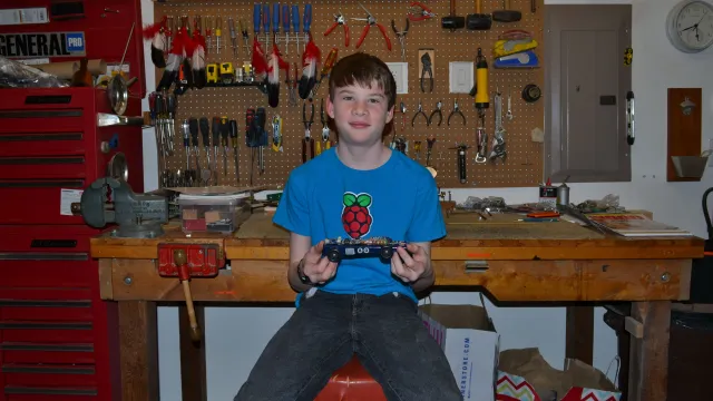
August: My dad and I had an idea that our last pinewood derby car should be really cool. My dad is a geek and really good with electronics so he did most of the coding. I did most of the design. I thought that it was a lot of fun because I got to spend more time with my dad and got to do a lot of things that I like. I couldn't wait until the race to see how fast it was. It did not win a single race. But we did win the most unique car design. It was the best Cub Scout experience I've ever had.
John: My son is in Cub Scouts and for years we've been building Boy Scouts of America Pinewood Derby (pinewoodderby.org) cars with the rest of the pack. I've always invited my son's Den into my workshop so the other scouts and their Dads can make use of my tools to build their cars. The Boy Scouts has a policy against Cub Scouts using power tools, but with the right guidance we've gotten along.
It's always…interesting to see how much involvement the Scouts have vs. their parents in making the cars. For the most part, I've let my son do what he wants with his car; I've guided him, but let him cut the car, sand it, paint it and so on. I really only got directly involved when it came to putting the wheels on as he didn't, until recently, have the physical strength and control needed to do that right.
After watching one particular parent last year spend two hours or more in the shop painstakingly cutting, shaping, sanding and grinding the car into a particular shape, my son and I decided that we'd kick it up a notch this year. Even though I have a pretty nice wood shop, I'm more of a programmer type (I've written 6 books on mobile development), so I suggested that we do something with a programmable microcontroller and some LEDs for this year's race. I'd wanted to do something with Arduino, so this seemed like the perfect opportunity to do so while at the same time providing me with a chance to teach my son how to wire things together, solder and write code.
In this project, we'll show you how to create an Arduino-powered Pinewood Derby car. We'll be using an Arduino (arduino.cc) microcontroller board, some LEDs and an accelerometer to flash a set of LEDs depending on the orientation of the car.
For our first iteration of this, we configured the car so that when it sits in the pits, it will flash the lights in a certain pattern. When the car is at the starting gate, and when it's on the angled portion of the track, the light pattern changes and becomes much more active. Knowing that the car may jump off the track, we also added special added patterns for when the car is sitting on its left or right side. Since everything is done in code, it's super easy to completely change the light patterns and orientation settings in the software. You and your son can spend hours trying out different patterns to get the right, and potentially unique, ones for your car.
Source Code
The project's Arduino source code available at https://github.com/johnwargo/Arduino-Pinewood-Derby.
Materials
The project uses the following materials:
- Official Pinewood Derby car kit (2 or more: if you're like me, you'll make mistakes and need to start over). Available at any hobby or craft store or at https://pinewoodderby.org/#/three.
- Arduino compatible microcontroller (1: for this project, I used a Teensy 3.0 https://pjrc.com/store/teensy3.html)
- Arduino compatible battery (adafruit.com/products/258)
- Battery charging module (adafruit.com/products/259)
- Power switch (adafruit.com/products/1400)
- Accelerometer (adafruit.com/products/163)
- LEDs (3.7 V or higher) with matching resistors (10)
- Ribbon cable (2 feet: https://sparkfun.com/products/10647)
- #2 wood screws (minimum 12: https://grainger.com, part #1LB35)
- #2 nylon washers (minimum 12: https://mouser.com, part #534-3347)
- Red and Black connector wire (24ga or equivalent)
- Prototype board (https://veroboard.com)
Tools:
- Pencil
- 12 inch ruler
- X-acto knife or similar
- ½ inch or smaller Chisel
- Soldering Iron & Solder
- Epoxy
- Paint, brushes, sandpaper
- Hand saw, band saw and/or table saw
- [optional] bench sander
Here are some details on the project’s components.
Arduino Board
The Arduino is an open-source programmable microcontroller. As its open-source, there are a lot of different versions of the board available. The Arduino team has designed some boards and different parts of the community have implemented their own designs. If you look on Maker Shed (https://makershed.com/collections/arduino-boards) you'll find a bevy of devices available of all sizes and capabilities.
You can use whatever Arduino compatible board you want, but since the Pinewood Derby car has specific requirements (confined by specific minimum and maximum length and width requirements as well as a weight limit), your choices will be limited based on what will actually fit on (or in) the car.
To prove that we could create the thing we wanted, we initially prototyped the solution using a breadboard and the Arduino Micro (https://makershed.com/products/arduino-micro). This allowed me to teach my son breadboarding and gave me a chance to get him involved in wiring the solution before we started soldering things together.
The Arduino Micro turned out to be too big for the project when you take into consideration all of the other components we needed to mount on the car as well. So I looked around for a smaller board we could use. I selected the Arduino Teensy (https://pjrc.com/teensy) because it was small enough and had all of the connections we needed. For this project, I used a Teensy 3.0; I purchased the board about a year ago. Since then, a newer version of the board was released and I'm sure there are other, suitably sized alternatives you can select for your version of this project. The Lithium Ion battery I used output 3.7 Volts, so I had to make sure the board I selected could operate on less than 5V.
For this project as configured, you'll need a board with minimum of 10 digital outputs and three analog inputs on whatever board you select.
Power
When we first started working on this project, I thought we'd power the car with one or more traditional alkaline batteries. We wired a battery pack into our solution and it worked great. As we started to figure out how everything would fit on/in the car and when we thought about the car's weight limitation, it quickly became clear that this wasn't an optimal solution. My son's a smartphone fanatic (even though he's too young to actually have a smartphone), so I started thinking about using a smartphone battery for this thing. A quick search pointed me to Adafruit's 3.7v 1200mAh Lithium Ion Polymer Battery (adafruit.com/products/258). It has enough juice to power the Arduino and LEDs plus run the car for several hours.
There are smaller (and bigger) batteries available, but for Pinewood Derby cars, it's important to keep in mind that for the best performing car you want the car's weight to be as close to the weight limit (5 ounces) as possible. With this battery and the other parts I selected, the car's total weight was 4.8 ounces, so we needed to add very little weight to the car to bring its weight up to the limit. If you select a smaller battery, keep in mind that you'll need to add weight if you want the car to perform as well.
My original plan was to disconnect the battery to charge it using an external charging module. My son and I started thinking of how cool it would be to have the car itself be rechargeable so we decided on the Adafruit USB LiIon/LiPoly charging module (adafruit.com/products/259). With the battery embedded in the bottom of the car and the charging module mounted on the back, you can charge the car using a standard cell phone charger. The charging module uses a USB Mini-B connector (rather than the modern Micro USB connector), so I had to dig out an older BlackBerry charger to use to charge the car.
Adafruit now has an even smaller charging module available (adafruit.com/products/1904) that uses a Micro USB connector, so this may be a better choice for your project. It looks to be the same size as the power switch (described in the next section), so it would be really easy to stack them together and take up very little space on the back of the car.
If you don't want to go the rechargeable route for this project, you could easily use the Maker Shed 9V Battery Case for Arduino (https://makershed.com/products/9v-battery-case-for-arduino). It should fit within the base of the car (although you'll have to make a taller car) and has a built-in power switch.
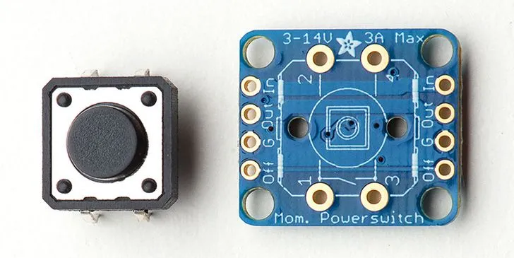
Power Switch
With power sorted out, it's time to think about how to turn the car on and off. In my original alkaline battery design, I expected that I'd use something like the Adafruit Breadboard-friendly SPDT Slide Switch (adafruit.com/product/805). Instead I selected the Push-button Power Switch Breakout (adafruit.com/products/1400). It has mounting holes, so I knew I could easily mount it on the car, and it's got an LED indicator underneath so it's easy to tell whether the car is powered or not (just in case something else isn't working) and the red glow just looks cool. The switch is a toggle switch, push it once to turn the device on and push it again to turn it off.
You can use something like the Maker Shed Tactile On/Off Switch with Leads (https://makershed.com/products/tactile-on-off-switch) but it doesn't have an indicator light and you would have to have to figure out a way to mount the device on/in the car.
Accelerometer
To allow the Arduino to measure the car's orientation, I selected the Adafruit ADXL335 5V ready triple-axis accelerometer (adafruit.com/products/163). Even though it's rated at 5V, it will operate at the voltages provided by the battery I selected. It has a small form factor and easily mounts on the front of the car.
Lighting
We had a lot of options for implementing the lighting for the car. In the prototype we made, we simply wired in 5 white LEDs, but we were looking for something more. I was looking for something a little more professional looking than some hand-wired LEDs, so I tried the Adafruit 8 LED NeoPixel Stick (adafruit.com/products/1426). If you're looking for something simple that will mount cleanly on the car, this is a good option as everything is already connected together and only uses only a few wires. It's also multi-colored, so that's pretty cool. It wasn't bright enough for our purposes and I had some issues getting the sample code to work correctly, so I discarded it as an option.
Instead we decided to just wire up 10 LED bulbs and I'll show you how we did that later. To do this, I purchased three sets of 3.7V LEDs, blue, yellow and orange; yellow and blue to match the Cub Scouts colors and orange simply because my son and I both like orange. I selected clear LEDs so that the LEDs all looked the same until they illuminate. You'll also need the appropriate resistors to use with the LEDs you select. For this project, I purchased LED/Resistor bundles from Amazon.com (blue: https://amzn.com/B004UZCADG, yellow: https://amzn.com/B004UZB9WO & orange: https://amzn.com/B004UZ3FNU).
Wiring
To connect the LEDs to the Arduino board, I purchased some ribbon cable; since I was connecting 10 lights, this ribbon cable was perfect https://sparkfun.com/products/10647.
The battery connected directly to the charging module, but I also needed to connect the charging module to the switch and from there to the Arduino board so I needed black and red connecting wire.
Making the Car
When it comes to creating the car, you can pretty much make it any way you want. The Scouts are supposed to make the car themselves (with your help, of course) so what you'll need to do is take a look at the components you'll be wiring together and build the car that can accommodate the configuration and layout you implement. This takes careful planning as your car design and electronics implementation are closely connected; you'll have to plan both in parallel.
Note: Be sure to check your Pack's Pinewood Derby race rules to make sure the car you create complies with them. Our pack for example has specific rules for width, height and weight plus we had to ensure that the rule about components being solidly mounted on the car were followed.
Figure 2 shows the car we created. In our implementation, the battery is underneath the car and all of the rest of the electronics are mounted to the top of the car as shown in the figure. You don't have to do it this way, we just selected this approach as it highlighted the electronics and that was what we were leading with; it was important that our car looked like it had a bunch of hardware on it.
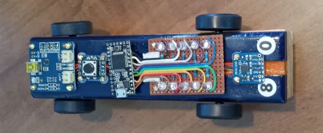
For your car, you may want to hide everything or only some components. You could for example, carve out a cavity for all of the components and only show the charging connector and the LEDs. For our race, I was concerned that someone would complain about potential cheating if anything was hidden, so I made sure that everything (except for the wires connecting the battery to the charging module) were easily visible. If any complaint was made, I could simply unscrew a few screws (12 total) and the whole thing would come off and could be easily inspected before being reattached to the car for a race.
Battery Cavity
Before you make any profile cuts to the car, you need to first make a space for the battery underneath the body of the car. Do this now so that the car's top can rest flat against your work surface as you complete these steps. If you make other cuts to the car's body before performing this step, you may find the car body rocking or slipping around as you cut the battery cavity.
To start, lay the car body on its top so that the axle slots are facing up. In the official Pinewood Derby kit, the car's rear axle slot is closer to the back of the car than the front axle slot is to the front of the car. As you work with the car, keep this in mind. Many cars are made backwards, with the car facing the wrong way – the front wheels using the rear axle slots.
With the car in this position, figure out where you want to put the battery. Conventional wisdom, feel free to disagree, is that you want the car's center of gravity to be right in front of the rear wheels. Select a position for the battery that makes the most sense for you and your car. Keep in mind that we'll soon be screwing electronic components to the car body, so you will want to make sure that the battery is placed in a position where you can minimize the chance that the screws will pierce the battery. For our car, we put the battery right in front of the rear axle.
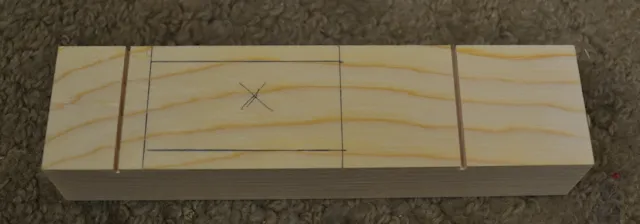
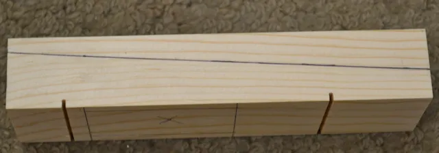
With the battery held against the bottom of the car, mark the battery's position by either placing marks at each corner or tracing the battery profile with a pencil. Remove the battery and use a ruler or some sort of straight-edge to mark the complete battery cavity. Be sure to leave a little extra space around the battery as we'll be using epoxy later to cement the battery in place and it will need some room to purchase. Be sure to also leave a little room at the top of the battery for the power cable. Figure 1 shows the results of this step on our car. The X in the figure marks the area of the car body that will be chiseled out.
Using an X-Acto knife or other hobby knife, trace the edges of the battery compartment you just marked. Make multiple passes and cut down to the approximate height of the battery.
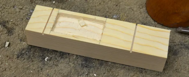
Using a chisel, cut away the wood within the cavity lines to the thickness of the battery as shown in Figure 4. When chiseling out the material, do as much of your carving away from the rear axle. When you carve toward the axle, you run the risk of cutting underneath the material between the battery cavity and the rear axle, popping off a chunk of wood between the two. If this happens, there won't be solid wood in place to hold the axle in place, so the car body will be ruined.
When finished, sand the cavity to smooth out any remaining rough spots. Place the battery in the finished cavity to make sure it fits and that it's flush with the bottom of the car.
With the battery in place, mark the location of the battery wires then remove the battery. Our battery came with a connector at the end, so we cut that off so that we'd have two unfinished wires coming out of the battery. This is probably not that important, but be sure to cut each wire separately to avoid shorting out the battery while you cut it.
Drill a small hole (big enough to feed the battery wires through) in the bottom of the car where you marked the battery wire location. This hole will be used to route the battery wires to the top of the car where the other components will be mounted. Make sure the hole is small enough for just the battery wires and that it goes straight through to where the other components will be.
When finished, you should be able to feed the wires through to the top of the car and insert the battery flush within the battery cavity.
Cutting the Car's Profile
For this car, we cut the body into the traditional Pinewood Derby wedge profile. May car kits already come in this profile, so it's a pretty popular design for many Cub Scouts, all they need to do is paint it, put on the wheels and they're ready to go. Here we had to make a slight adjustment to the thickness of the wedge in order to accommodate the 1/2 inch screws we used to attach the components to the car.
Using a pencil, mark the side of the car with the wedge design, making sure that the car's thickness doesn't fall below 1/2 inch at the front of the car as shown in Figure 5. In the figure, the back of the car is to the left of the image. To make this easy, I marked the front of the car at 1/2 in and drew a line to an arbitrary point on the back of the car, enough space to accommodate the battery height and length of the mounting screws.
Note: when it comes to cutting the car's body, use caution when making the cut. I do not recommend you allow your son to make the cut – you should make it using the appropriate safety precautions and necessary safety gear. I let my son cut his Pinewood Derby car on the band saw, but only under my direct supervision. Whether or not you let your son use power tools is up to you (not me).
Cut the car on the band saw using the line drawn on the car's side. Be sure to wear safety glasses. Next, use a bench sander to smooth out any roughness in the cut and flatten the car's top.
We knew that there was going to be some wires routed across the top of car (connecting the different components), so we cut a trough in the top of the car about 3/8 inch wide and about 1/4 inch deep. I used my table saw for this, but you could easily do this with a Dremel or Router.
Using the saw, I set the blade's height to the cut depth I wanted and positioned the saw's fence to position my first cut right down the middle of the car. After running the car across the saw for the first cut, I moved the fence away from the blade by about a blade width and ran the car across the blade two more times (flipping the car around between cuts). This gave me two more cuts, one on either side of the original one. I repeated this process until I had a trough cut that matched the width I needed. I could also have made this cut in a single pass using a dado blade, but it was more fun to do it this way and taught my son a few things about the table saw.
One of the things we didn't do, but you should, is round out the front of the car to make it more aerodynamic going down the track (and cooler looking too). Be careful to not shorten the car by cutting material off the front of the car, your Pack's rules may not allow it.
At this point, the car body is ready; sand and smooth the remaining edges as needed then paint the car and put it aside to dry.
Wheels
Over the years, I've always made my son put the wheels on his car at the last minute, right before we headed to the race. I did this because I know that wheel placement is critical to car performance, and if I put the wheels on too early, my son would play with the car and whack the wheels out of alignment, ruining the car's chances in the race.
When we built this car, the same rule applied and the night before the race we were putting the wheels on and struggling. We needed to manhandle the axles into the car and I quickly noticed a problem I created when we added the electronics to the body. In order to be able to insert the wheels, you have to hold the car pretty tight while doing so. Electronic components can be fragile, and I was worried that I might smash something or break a connection if I held the car too tight while putting on the wheels. I had a tough time with the wheels and axles simply because I was afraid of holing the car too tight while putting them in.
I learned that in this case, it made sense to put the wheels on early, before mounting all of the electronic hardware on top of the car. That way I could hold the car as hard as I wanted as I worked.
But how to protect the wheels after they're on the car? I came up with an excellent solution (one I wish I had come up with years ago). When you pick up your son's car kit, pick up a couple of extra ones. You're going to make a mistake, so be sure to have a couple of extra ones on hand just in case. Once the wheels are on, though, take an extra car body blank and keep it under the car (you can see an example of this if you look closely at Figure 2) at all times. It's the exact same size as the car you're working with and it's flat on top and bottom. You can even tack small pieces of wood on the front and back of the blank to keep the production car on place on top of the block.
Connecting the Electronic Components
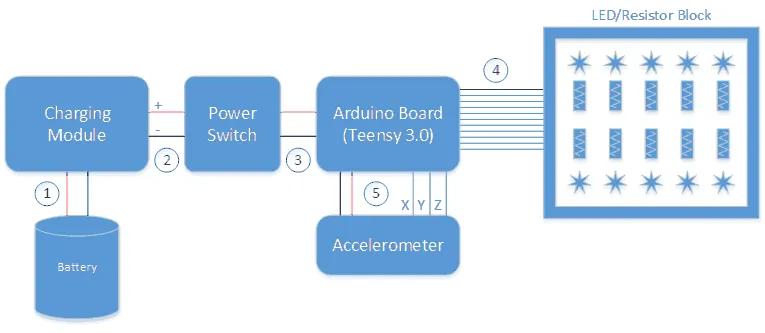
Now that you have a car design, it's time to start assembling the electronic components. Figure 6 shows a high-level illustration of how everything wires together. I've labeled the figures with numbers indicating the different steps in the connection process. The figure shows a logical connection diagram, how each individual component connects to its peers. In reality, part of the wiring for steps 4 and 5 are combined together in order to simplify the wiring.
Note: Then making connections between the components, be sure to use the appropriate length wires to enable the particular layout you have selected for your vehicle. You don't have a lot of space to work with on/in the car, so things will likely be a little tight. As I soldered things together, I tried to use the shortest possible wires in order to minimize any chaos on top of the car.
The charging module is smart enough so that you plug a rechargeable battery into it and wire the charging module to the electronic components that need electricity. When the charging module is plugged into a cell phone charger or USB cable, it will charge the battery and pass the appropriate voltage onto the electronic components. When you disconnect the charger, the battery provides voltage to the electronic components.
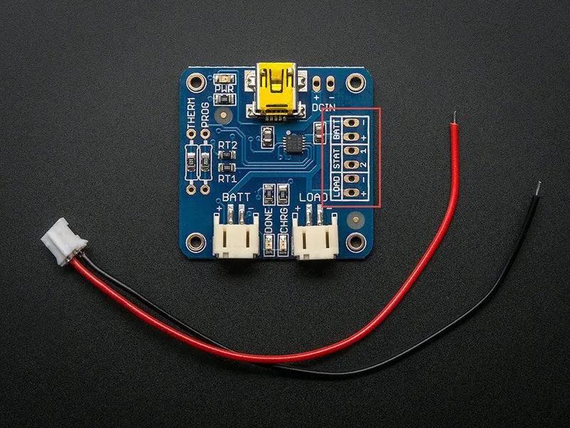
Step 1: Pass the battery wires up through the hole you drilled in the bottom of the car and solder them to the input pins on the charging module. The battery connects to the BATT connectors shown in the top right of Figure 7 (highlighted in a red box in the figure). Solder the battery's red wire to the charging module's + (positive) BATT connector. Solder the battery's black wire to the charging module's – (negative) BATT connector.
Step 2: Begin by soldering the pushbutton to the switch module shown in Figure 8. The top and bottom connectors on the pushbutton (left) solder into the top and bottom module connections (right) in the figure.
The power switch takes two wires (positive and negative) wired to the input connectors and another two off of the output connectors. The connections are the same on both sides of the module, so for this step, pick one side of the module and make both connections to the same side. Solder a red wire from the charging module's + (positive) LOAD connector (Figure 7) to the switch's In connector. Solder a black wire from the charging module's – (negative) LOAD connector to the switch's G (ground) connector.
Step 3: The pin layout for the Teensy 3.0 microcontroller is shown in Figure 9 (Image used with permission); for this project, we'll be connecting a bunch of stuff to it.
At any point in the process from here, you can secure the battery in the battery cavity on the bottom of the car. You could use a non-permanent approach like duct tape or suitable alternative to hold it in place, but as there might be collisions and the battery could pop out, I decided to take a more permanent approach. For this project, we used Epoxy to cement the battery into the cavity. Make sure the battery is flush with the bottom of the car and that there's a little space between the battery and the car body. For epoxy, I used https://homedepot.com/p/Loctite-8-fl-oz-Professional-Job-Size-Epoxy-1365736/100371835 but you could also use something like https://homedepot.com/p/Loctite-0-85-fl-oz-Quick-Set-Epoxy-1395391/100371815. Mix an enough epoxy to fill the gaps between the battery and the car body and spread it over the cavity, covering enough of the battery to hold it in place. Only use enough epoxy to cover the gaps and make a smooth cover flush with the bottom of the car.
Note: Keep in mind, that once the battery is epoxied in there, it's not coming out without destroying the car, so plan carefully.
Step 4: At this point, it's time to connect the Accelerometer and the LEDs to the Arduino. Because of the amount of available space on the car, we positioned the accelerometer on the front of the car and the block of LEDs between it and the Arduino board as shown in Figure 2. If you look at Figure 6, you should be able to see that both the Accelerometer and the LED block have one common connection: the (black) ground wire. To simplify the wiring, I decided to use a single ground wire and share it across both devices. To do this, cut a length of black wire long enough to connect from the Arduino GND pin on the middle-right side of the board shown in Figure 9 to the front of the car. Don't worry about making it too long, you can always trim it back later. Strip the insulation off of one end and solder the wire to the Arduino GND pin.
Next you'll need to prepare wires to connect the Arduino board to the Accelerometer and to create the block of LEDs.
First measure out two lengths of the 10 wire ribbon cable, select a length that will be able to connect from the Arduino board all the way to the front of the car. That's longer than is needed, but you'll trim them back as you wire together the rest of the car.
Strip the ends of one of the ribbon cables and solder the wires to pins 0 through 9 on the bottom of the Arduino board shown in Figure 9. These wires will eventually connect to the LED block as shown in Figure 12.
Remove most of the wires on the other section of ribbon cable, leaving only 4 wires. I recommend leaving the red wire and three other colors if possible. One of those wires is for providing voltage to the accelerometer and you might as well keep the color convention used so far and use the red wire for that connection.
Strip the ends of the 4-wire ribbon cable and solder the red wire to the 3.3V pin shown on the right side of Figure 9. Next, solder the remaining three wires to Arduino pins 14 (A0), 15 (A1) & 16 (A2).
At this point, you'll have one black ground wire and two ribbon cables (one 10-wire and a 4-wire cable) connected to the Arduino board. Now we'll need to assemble the block of LEDs. In our design, the lights were mounted right next to the Arduino board and the accelerometer was positioned at the front of the car. So, the 10 wire ribbon cable will connect directly to the LED block while the 4-wire ribbon cable will travel underneath the LED block to the accelerometer at the front of the car. Don't forget too that the LED block and the accelerometer are going to share the ground connection provided by that lone black wire you have connected to the Arduino's ground.
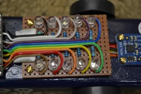
To create the LED block, I cut a piece of prototyping board to fit the top of the car body and allow me to fit all 10 LEDs and their associated resistors as shown in Figure 10. I positioned the LEDs on the outside of the board and positioned the resistors in the middle of the board wired into the black ground wire. The ground wire connects the resistors to ground underneath the board while the ribbon cable travels across the top of the board and each wire splits off to connect to the + wire of each LED.
Note: I used a block of two-sided tape (shown under the ribbon cable on the left of Figure 10) to hold the ribbon cable in place as I made the connections.
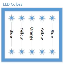
For our car, we used three different color LEDs: blue on the outside, yellow just inside the blue and orange in the middle as shown in Figure 11. There are 4 blue and yellow LEDs and only 2 orange ones. The LEDs are clear so when the car is off, you can't tell what colors are used. You can, of course, use whatever colors and patterns you want for your car.
If you look at Figure 12 you'll see a logical wiring diagram that shows how the different components are connected.
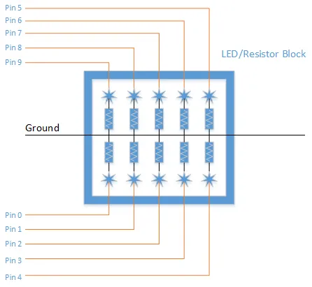
On the board, each LED's negative lead (shorter wire) is soldered to the nearest resistor lead. Then the other resistor lead is soldered to the ground wire. To make this work cleanly with the one ground wire, I used a knife to strip all of the insulation off the ground wire between the first and last resistors. Where the resistors come through the board, I wrapped the leads from two aligned resistors around the ground wire and soldered them in place. This was the easiest way for me to use a single ground wire for all of the LEDs as well as the accelerometer.
Next, I put a piece of double-sided tape on the board and connected the ribbon to it. This allowed me to split off each of the wires and connect each wire to the individual LED + lead (the longer wire) as shown in the two previous figures. Solder the ribbon cable wires to the LEDs using the pattern (pin layout) shown in Figure 12. The pin numbers shown in the figure correspond to the connections shown in Figure 9. If you wire yours differently, you'll have to make some minor changes to the application source code shown later in the article.
Step 5: Now, cut the remaining length of the black ground wire to fit the location of the accelerometer on the car then strip the end and solder the wire to the ground connection (GND) on the accelerometer shown in Figure 13.
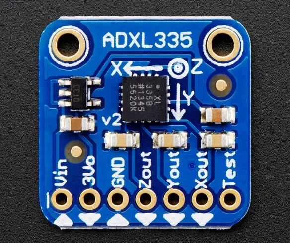
Cut the 4-wire ribbon cable to length then strip the wire ends and solder them to the accelerometer. Solder the red wire to the voltage input (Vin) connector on the accelerometer. Solder the remaining wires to the Xout, Yout and Zout connectors on the accelerometer shown in the figure. In our configuration, we have the accelerometer's X output to the Arduino pin 14, Y output to pin 15 and Z output to pin 16. If you wire yours differently, you'll have to make some minor changes to the application source code shown later in the article.
Mounting the Hardware
With everything wired up, you could go ahead and mount all of the components to your car body, but then you'll be jinxing things (I never screw a PC case cover on until after I'm certain everything works, otherwise I know I'll just be taking them off again to troubleshoot). In our configuration, we used the #2 screws to mount everything but the Arduino board to the car. Add nylon spacers under components as needed to help ensure there's enough space for wires and the ribbon cable to route between components without pinching.
There weren't any mounting holes on the Teensy to use and the ribbon cable pretty much holds the board in place. You could use brads or a small nail to nail the board to the car body, but that didn't seem to be necessary.
I used epoxy to hold the battery securely in the battery cavity in the bottom of the car. You could use double-sided tape or even duct tape to hold it in place; I went for the permanent solution so I would never have to worry about it falling out in a crash.
Setting Up the Development Environment
In order to program an Arduino board, you need to use the free Arduino IDE. The Teensy board I used for this project requires some extra software, Teensyduino and the Teensy Loader, in order to be able to download applications onto the board. Unfortunately, as I write this, the latest version of the Teensy Loader is not compatible with the latest version of the Arduino IDE; it can only work with Arduino IDE version 1.06. So, point your browser of choice to https://arduino.cc/en/Main/OldSoftwareReleases then download and install Arduino IDE version 1.06.
You'll also need to install the https://pjrc.com/teensy/teensyduino.html in order to enable the IDE to see the Teensy board.
Next, download and install the latest version of the Teensy Loader from https://pjrc.com/teensy/loader.html.
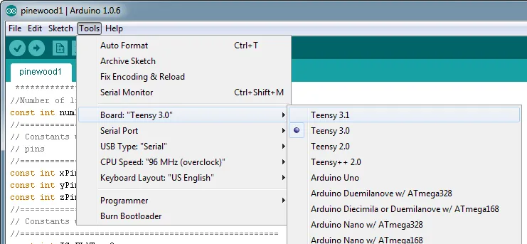
With all of the software installed, open the Arduino IDE. You'll first need to configure the IDE so it knows what board you are working with. Open the tools menu and select the appropriate Teensy board as shown in Figure 14.
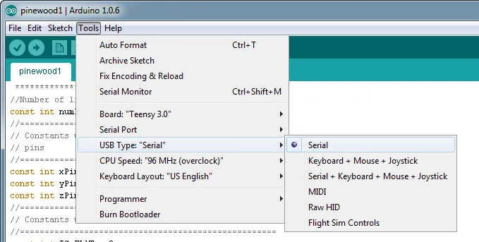
You'll also need to configure the IDE so it knows how to communicate with the board. Open the Tools menu again and make sure USB Type: Serial is selected as shown in Figure 15.
With the software in place, download this project's code from https://github.com/johnwargo/Arduino-Pinewood-Derby. Once you have the code, open the Arduino IDE then open the downloaded project file called pinewood1.ino.
Connect a USB cable from one of the USB ports on your computer system to the Micro USB cable on the Arduino board. If you followed the instructions in this project, you'll actually have two USB ports available to you, one on the charging module and another on the Arduino board. Be sure to plug the USB cable to the one on the Arduino board (shown in Figure 9).
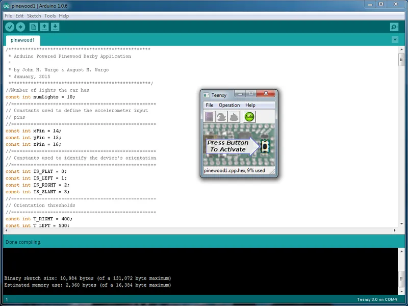
You can compile the application code by clicking the checkmark button in the upper left corner of Figure 16. You can also compile and load the application code onto a connected Arduino board by clicking the right arrow button to the right of the checkmark button.
When you do this, the Teensy Loader window will open as shown in the figure. The first time you to this, you'll need to press the small black button on the Teensy Board to reset the board and initialize the loader. Once you've done that, the code should download into the board every time you click the deploy button in the IDE.
If everything went well with your assembly, the LEDs should start blinking away. If you wired the LEDs or the accelerometer into different pins, you'll need to change the code before you can run the application. Refer to the next section for a detailed analysis of the application code and what you'll need to change.
The Code
In this section, I'll walk you through portions of the project's Arduino source code. The complete source code for the project can be found at https://github.com/johnwargo/Arduino-Pinewood-Derby.
The code starts by defining some constants used by the application:
//Number of lights the car has
const int numLights = 10;
//====================================================
// Constants used to define the accelerometer input
// pins
//====================================================
const int xPin = 14;
const int yPin = 15;
const int zPin = 16;
//====================================================
// Constants used to identify the device's orientation
//====================================================
const int IS_FLAT = 0;
const int IS_LEFT = 1;
const int IS_RIGHT = 2;
const int IS_SLANT = 3;
//====================================================
// Orientation thresholds
//====================================================
const int T_RIGHT = 400;
const int T_LEFT = 525;
const int T_SLANT = 470;

int blueLights[4] = {0,4,5,9};
int orangeLights[2] = {2,7};
int yellowLights[4] = {1,3,6,8};

int i = 0;
The numLights constant is used to manage the process of looping through all of the lights. Whenever the application needs to do something to all of the lights, to turn them all on or all off for example, you'll see something like this:
for (i = 0; i < numLights; i++) {
  //do something here

}
For my code, I wired the LEDs to the Arduino's digital output pins beginning with pin 0, this is what allows me to easily loop through all of the lights using this code. It's important that the lights are wired sequentially, beginning with pin 0, as shown in Figure 12 in order for this code to work. If you wired the lights to a different starting pin, you'll need to change the affected for loops everywhere so that the loop begins with the first digital output pin you used.
In order to make the code more readable, I defined constants for each of the accelerometer inputs:
// Constants used to define the accelerometer input
// pins
//====================================================
const int xPin = 14;
const int yPin = 15;
const int zPin = 16;

If you connected the accelerometer Xout, Yout or Zout pins differently than is described earlier in this article, you will need to change the values here to align with how your device is wired.
I defined constants for the different orientations the application will react to:

//====================================================
// Constants used to identify the device's orientation
//====================================================
const int IS_FLAT = 0;
const int IS_LEFT = 1;
const int IS_RIGHT = 2;
const int IS_SLANT = 3;
This makes the code a little more readable and allowed me to implement a simple switch statement to branch on the different orientations.
As I tweaked the car so that the program could react to different orientation thresholds, I defined the threshold values as constants at the beginning of the application so that I wouldn't have to hunt for them when I needed to make changes.
//====================================================
// Orientation thresholds
//====================================================
const int T_RIGHT = 400;
const int T_LEFT = 525;
const int T_SLANT = 470;
Change the values here to affect what accelerometer reading switches the car from flat mode to left, right or slant mode.
I also defined arrays for each of the light groupings (blue, yellow and orange) so that the application would have an easy way to affect all lights of the same color simultaneously:
int blueLights[4] = {0,4,5,9};
int orangeLights[2] = {2,7};
int yellowLights[4] = {1,3,6,8};
When you look later in the code, you'll see that I made separate functions for affecting each light grouping. I know I could just pass an array to a function and have the function affect all lights defined by the array, but I was trying to keep the code simple for my son and not try to get into array passing (which seems to be challenging to do in Arduino C).
With all of the application's constants defined, it's time to jump into the code.
The setup function initializes the application and the car's hardware:
void setup() {
   //Set all of the pins to output mode
  for (i = 0; i < numLights; i++) {
    pinMode(i, OUTPUT);
  }
  //make sure all of the lights are off
  doAll(LOW);
  //Grab the initial value off of the accelerometer
  //this will be disgarded. Eliminates a quick light
  //lighting issue when the device is first turned on
  int tempInt = getOrientation();
  //Do a short delay before doing anything else
  delay(500);
  //Flash all of the lights (twice)
  doBlinkBlink();
}
The code starts by setting all of the pins used by the LEDs to OUTPUT mode. These statements instruct the Arduino on how to deal with those 10 pins.
Next the application calls a simple function called doAll to make sure that the output voltage for all of the LED pins is LOW (0). I found that the Teensy board automatically turned one of the pins on, so I had to add this call to setup to make sure that the car started with all lights off.
Another thing I noticed is that the accelerometer would sometimes start with rogue values for the X, Y and/or Z axes, so during setup I had the application read all initial values from the accelerometer then discard them. If I didn't do this, the car would often start by displaying one of the light patterns when in reality the car was sitting flat.
Just for fun, I then had the code wait for half a second (500 milliseconds) then flash the lights twice to get everyone's attention before doing its light thing.
After setup executes, the Arduino will repeatedly execute the loop function. Anything the car needs to do has to be coded here:
void loop() {
  //make sure all of the lights are off
  doAll(LOW);
  //Read the accelerometer
  int orientation = getOrientation();
  //Now do something based on the orientation
  switch (orientation) {
  case IS_LEFT:
    doAllRight(100);
    break;
  case IS_RIGHT:
    doAllLeft(100);
    break;
  case IS_FLAT:
    doCycle(125);
    break;
  case IS_SLANT:
    doBlend(75);
    break;
  default:
    //This should never execute
    //make sure all of the lights are off
    doAll(LOW);
  }
}
The function first sets all lights to off, something I probably didn't need to do, but I learned a long time ago never to assume any state within an application. Next, the code reads the accelerometer then fires off a function to blink the lights in a certain pattern depending on the car's orientation. If you want to make your own patterns, simply code the function that implements it and change the loop function so your function (or functions) are called when the car is in a particular orientation.
You can also add additional orientations by adding the appropriate constants at the beginning of the code, add the appropriate case statement to the loop function and modify the getOrientation function (described below) so it can determine the orientation you want the car to react to.
In the application's getOrientation function, the code reads the accelerometer then uses the different threshold constants to determine the car's current orientation:
int getOrientation(){
  int x = analogRead(xPin);
  int y = analogRead(yPin);
  int z = analogRead(zPin);

  //Are we flat in the X direction?
  if (y > T_SLANT) {
    //Are we on our right side?
    if (x < T_RIGHT) {
      return IS_RIGHT;
    }
    //Are we on our left side?
    else if (x > T_LEFT) {
      return IS_LEFT;
    }
    else {
      //We must be flat
      return IS_FLAT;
    }
  }
  else {
    //We're slanted
    return IS_SLANT;
  }
}
The code compares X or Y accelerometer values to determine whether any of the thresholds have been crossed then returns the appropriate constant to the loop function so it can execute the appropriate function based on the orientation. I could have put all of this code into the loop function, but that would have complicated things and made it harder to read. It was easier to demonstrate the code's functions in smaller chunks so my son could more easily understand what was going on.
You may be wondering how I knew what threshold values to use. When I had everything wired up and working, I wrote some code that simply outputted the accelerometer values back to the Arduino IDE. In the setup function, I added the following code:
Serial.begin(9600);This told the application to open the serial port for output. Next, in my getOrientation function I added code that outputted the axis and value using the following:
Serial.print("X: ");
Serial.println(x);
Serial.print("Y: ");
Serial.println(y);
Serial.print("Z: ");
Serial.println(z);
I then moved the car around and watched the different values on the screen. That's how I was able to determine which accelerometer value (x, y or z) was being affected and what threshold value to use. Once I had all the numbers I needed, I removed that code and was all ready to go.
That's it; at this point, the car knows how to turn the lights on/off and is able to determine its orientation via the accelerometer. All that's left is to fire the lights.
To simplify things, I made some helper functions I could use different ways in the code. The setLightStatus allows me to set a range of lights to a particular state (on or off). In the following example, I'm setting lights 5 through 9 to on (HIGH):
setLightStatus(5, 10, HIGH);

//====================================================
// Turn on/off a range of lights
//====================================================
void setLightStatus(int theStart, int theEnd, int theStatus) {
  for (i = theStart; i < theEnd; i++) {
    digitalWrite(i, theStatus);
  }
}
As described previously, I can affect all lights using:
doAll(LOW);  //turns all lights off
doAll(HIGH);  //turns all lights on

//====================================================
// Turn on/off all of the lights
//====================================================
void doAll(int status){
  setLightStatus(0, 10, status);
}
When the application first runs, it blinks all of the lights twice using:
//====================================================
// Flash all of the lights twice
//====================================================
void doBlinkBlink(){
  doAll(HIGH);
  delay(200);
  doAll(LOW);
  delay(100);
  doAll(HIGH);
  delay(200);
  doAll(LOW);
}
This is, I know, very low tech, but it was a nice simple example for my son to comprehend.
When the car is flat on a surface, it cycles through all of its lights in sequence using:
//====================================================
// Loop through the lights
// timeDel controls how long the each light stays on
//====================================================
void doCycle(int timeDel){
  for (i = 0; i < numLights; i++) {
    //Loop through all of the pins and turn the light on
    digitalWrite(i, HIGH);
    //Then wait for timeDel milliseconds
    delay(timeDel);
    //Then turn the light off
    digitalWrite(i, LOW);
  }
}
This is an example of where starting my digital output pins at pin 0 allowed me to create a simple for loop to process all lights in sequence. In this function, I pass in a timeDel variable that tells the function how long to keep each light on (in milliseconds). You could modify this so that the light spends an equal amount of time off by adding another delay after turning the light off.
I made separate functions for turning each light group on:
//====================================================
// Turn on all of the Blue lights
// then wait a little bit
//====================================================
void doAllBlue(int timeDel){
  for (i = 0; i < 4; i++) {
    digitalWrite(blueLights[i], HIGH);
  }
  delay(timeDel);
}

//====================================================
// Turn on all of the Orange lights
// then wait a little bit
//====================================================
void doAllOrange(int timeDel){
  for (i = 0; i < 2; i++) {
    digitalWrite(orangeLights[i], HIGH);
  }
  delay(timeDel);
}

//====================================================
// Turn on all of the Yellow lights
// then wait a little bit
//====================================================
void doAllYellow(int timeDel){
  for (i = 0; i < 4; i++) {
    digitalWrite(yellowLights[i], HIGH);
  }
  delay(timeDel);
}
Then I cycled through each light group using the following:
//====================================================
// Light the lights in bands, blue first, then
// yellow, to orange and back again.
//====================================================
void doBlend(int timeDel){
  doAllBlue(timeDel);
  doAll(LOW);
  doAllYellow(timeDel);
  doAll(LOW);
  doAllOrange(timeDel);
  doAll(LOW);
  doAllYellow(timeDel);
  doAll(LOW);
  doAllBlue(timeDel);
}
This code lights each light group for a certain amount of time (passed in the timeDel variable): Blue then yellow, then orange, then yellow and finally blue again. This is the frenetic pattern I used when the car is sitting in the starting gate.
Wrap-Up
The cool thing about this project is that there's a lot more that you can do with it. In this article, we showed you how to build and program the electronics, but what you do with it is all up to you. You can make your own light patterns and pair the electronics with the fanciest (or simplest) car your imagination can come up with.
I know that with the appropriate accelerometer and/or gyroscope you can use it to determine whether a device is in motion – since my son and were just getting into this, I focused on orientation rather than motion. A cool enhancement to this is to flash the lights in an even more frenetic pattern while the car is in motion.
I'm sure that you can write much cleaner and more concise C code for your project. Remember, that what I did here was more for educating my son than showing how well I can write code.
I'd like to maintain a public gallery of the different cars you create from this article, so when you have your car running, send me a tweet with a picture or video link to @johnwargo and I'll publish them somewhere.
Next and/or Previous Posts
<< Nexus Support Euphoria Particle Garage Door Opener Code Published >>
Header image: Photo by Robin Glauser on Unsplash.