 John M. Wargo
Relay Testing Jig

Posted: June 21, 2016 | | Categories: Raspberry Pi, Internet of Things (IoT)
I've been doing a few projects lately that work with relays. One was a Particle Photon project that I hope to write about soon, and the other is a Raspberry Pi project that I've not completed yet. As I worked on each of these projects, I found myself wiring up one or more LEDs and connecting it to the microcontroller so I could validate whether the code is working correctly. Yes, I know I could tell the relay is firing by the click it makes when I fire it, but I wanted something visual.
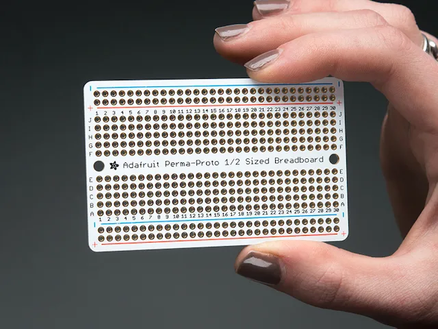
Anyway, while browsing around on the Adafruit web site, I discovered their Perma-Proto boards (https://adafruit.com/products/591). These things are breadboards (of a sort) that you solder components into. They're a nice, easy way to quickly build projects in a more permanent way.
I bought a handful and they sat around for a while looking for something to do. As I wired up yet another LED configuration, I remembered these boards and started thinking. I decided to create a relay testing jig using a proto-board, some LEDs, resistors and a battery. You can see the finished project in the following figure.
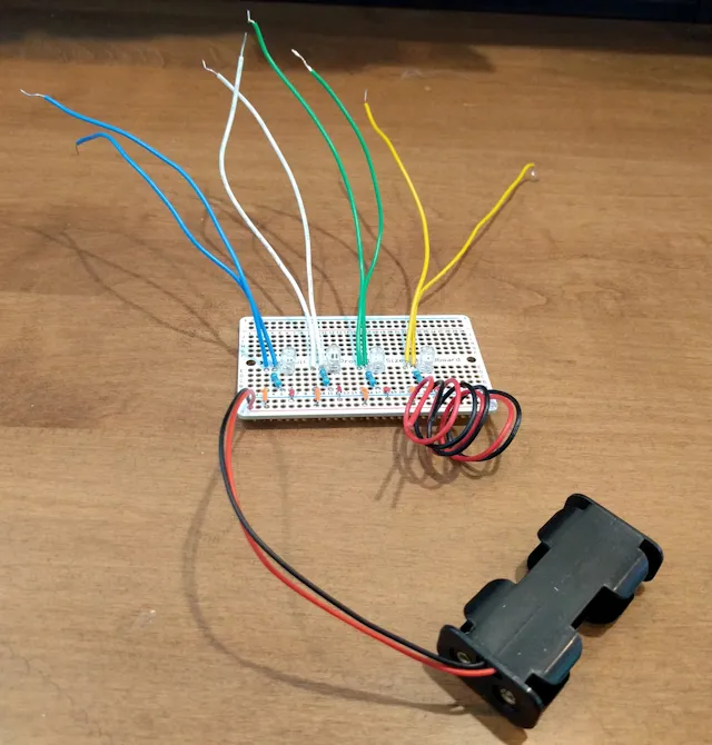
The battery provides power for each of the LEDs, but the negative wire to the LED is broken (the pairs of colored wire at the top of the figure). When you put AA batteries in the holder then collect one or more pair of colored wires to a relay, you have a simple jig you can easily wire in to help you test the software before you finish building the final hardware project. Connect both wires of the same color to the relay's NO or NC connections and you're set.
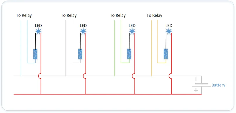
Here's a rough circuit diagram. My long term goal (who knows, perhaps it will become a short term goal) is to learn how to use Fritzing. Once I do, I'll come back and provide a circuit diagram for this project so you can easily create your own.
Now, whenever I'm working on a project, I can grab this jig and be up in running in seconds.
My plan is to make another one that I'll use for testing GPIO ports on a microcontroller. This version will not be battery powered, but will instead get its power from the controller whenever the connected GPIO port goes high.
Next and/or Previous Posts
<< Defective Astro Pi Sense HAT Boards Pi Reminder Updates >>
Header image: Photo by Harrison Broadbent on Unsplash