 John M. Wargo
Driving a Relay Board from Python Using GPIO Zero

Posted: March 25, 2017 | | Categories: Raspberry Pi, Internet of Things (IoT)
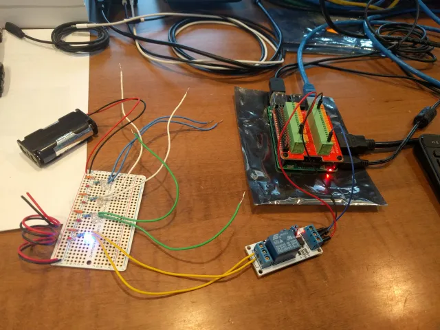
As you may have noticed, I've been working on a few projects lately that use relays. A while back, I bought some single, double and quad relay boards from yourduino.com (in China, I think). They were pretty inexpensive and I thought they'd work well for some of my projects. I never got around to using them – mostly because there were some jumpers on the board and no instructions and I really didn't have the patience to figure out how they worked.
Anyway I got this cool Paddle Breakout HAT from ModMyPi, so I had an easy way to wire up the Pi to the relay board. I connected the relay board to the Pi's 5V output, Ground, and GPIO pin 18 then wrote a simple app to test it out. It worked! First try. Here's a picture of the setup, the board on the left is the relay testing jig I wrote about here.
I created a GitHub Gist with the code, you can find that here in an easily digestible format: https://gist.github.com/johnwargo/ea5edc8516b24e0658784ae116628277.
The code uses the GPIO Zero library to interact with the relay board. You basically define an output device using the following code:
relay = gpiozero.OutputDevice(18, active_high=False, initial_value=False)Then, you turn the relay on by executing:
relay.on()And turn the relay off by executing:
relay.off()It couldn't be simpler. Toggling the relay is easy too, just make a call to:
relay.toggle()The GPIO Zero library takes care of tracking relay status automatically.
The relay board comes configured by default to trigger the relay when the input voltage goes low, so that's why the output device initialization includes the active_high=False parameter. The initial_value=False simply makes sure the relay starts in an off status.
Here's the complete source code listing for the app:
#!/usr/bin/python

# A simple Python application for controlling a relay board from a Raspberry Pi
# The application uses the GPIO Zero library (https://gpiozero.readthedocs.io/en/stable/)
# The relay is connected to one of the Pi's GPIO ports, then is defined as an Output device
# in GPIO Zero: https://gpiozero.readthedocs.io/en/stable/api_output.html#outputdevice

import sys
import time

# Make sure you install required libraries:
# https://gpiozero.readthedocs.io/en/stable/installing.html
import gpiozero

# change this value based on which GPIO port the relay is connected to
RELAY_PIN = 18

# create a relay object.
# Triggered by the output pin going low: active_high=False.
# Initially off: initial_value=False
relay = gpiozero.OutputDevice(RELAY_PIN, active_high=False, initial_value=False)


def set_relay(status):
    if status:
        print("Setting relay: ON")
        relay.on()
    else:
        print("Setting relay: OFF")
        relay.off()


def toggle_relay():
    print("toggling relay")
    relay.toggle()


def main_loop():
    # start by turning the relay off
    set_relay(False)
    while 1:
        # then toggle the relay every second until the app closes
        toggle_relay()
        # wait a second
        time.sleep(1)


if __name__ == "__main__":
    try:
        main_loop()
    except KeyboardInterrupt:
        # turn the relay off
        set_relay(False)
        print("\nExiting application\n")
        # exit the application
        sys.exit(0)
Next and/or Previous Posts
<< Ridiculous IBM Password Form Tim the Enchanter >>
Header image: Photo by Harrison Broadbent on Unsplash