 John M. Wargo
Particle Photon and the National Control Devices Relay Board

Posted: July 1, 2018 | | Categories: Internet of Things (IoT)
Links On This Page
If you've read my most recent stuff in Make Magazine (4 Ways to Control Electronic Relays), you know I like working with relays. One of the projects I showed in that article is a garage door opener project I built using a Particle Photon and a relay controller from a company called Control Everything. I needed to build a couple of these devices for some family and friends, but my original relay board is no longer available. Control Everything is now National Control Devices, and the small and simple Photon Relay board is now the 1-Channel 1-Amp SPDT Signal Relay Board + 7 GPIO with IoT Interface.
Just in case you're interested, here's the specs (from the NCD website) on the new board:
- 1-Channel Relay Controller with IoT Interface
- 7-Channel Programmable Digital Input/Output (GPIO)
- Compatible with Electron, Photon, Bluz, or RedBear
- Adaptable to Onion, PyCom, Raspberry Pi, Arduino
- MCP23008 I2C Controlled Mechanical DPDT Relay
- Choose 1, 3, or 5-Amp DPDT Signal Switching Relays
- World's Most Expandable Controller with I2C Expansion Port
- Wireless Remote Operation with Key Fob Expansion Option
- ESP8266 and USB IoT Interface Modules are Also Available
- IFTTT Firmware Available for Internet Relay Control
- Example Libraries Available on GitHub
Missing Documentation
As you can see, one of the features of this board is the GPIO ports it exposes along with a relay, they give me the ability to control some LEDs along with switching the relay. You can also use those GPIO ports as inputs, but for my project, I wanted to use them as outputs (driving two LEDs).
As I started assembling my hardware, I noticed that a lot of information you need to interact with the relay board is missing from the product's sparse documentation. Specifically, there was no information available on how to use the GPIO functionality on that board.
I let the folks at NCD know, and asked them to update the docs, but what I heard back was “Honestly I wrote these libraries a long time ago and that functionality just wasn't something I thought of at the time. We release these libraries to the public for free so we really don't make a whole lot for developing them which limits the amount of time we as a business can invest in updating them for feature additions.”
So, basically, they're saying it's not worth their effort to update the docs so you'll know how use their products. Nice!
I fixed some typos in their docs and submitted pull requests, but so far they've not accepted them or even responded to let me know that they won't use them. Sigh.
With that in mind, I thought I'd fill in some of the blanks in the docs so if you buy one of these boards, you'll actually be able to use it to its full extent in your project.
Mounting the Photon
The original relay board only supported the Photon, so it was easy to mount the photon to the relay board. The board came with markings indicating which end of the photon went where.
The NCD documentation doesn't include any instructions for how to connect the Photon to the relay board, nor are there any product pictures using the Photon. The new relay boards accommodate a wider variety of microcontrollers (adding the Electron, Bluz, or RedBear) which have more pins (connectors) than the Photon, so the relay board has more sockets than the Photon has pins.
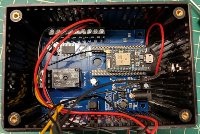
So, if you look at this image (which shows a microcontroller I don't recognize), it's using all the sockets. The photon aligns with the far right of the board (as shown in the figure) with the Photon's power connector pointing off the end of the board. When you mount the board, make sure the first pins on the board insert in the sockets at the edge of the board. When you're done, there will be a bunch of sockets open to the left of the Photon.
Normally I'd simply take a picture of my hardware, but I've already completed assembly of my project and I'd have to take it apart to grab a photo. I had a reason to take the project apart, so here's a photo that shows how the Photon fits on the relay board.
Using the GPIO Ports
Now, here's where it gets funny. NCD calls the single relay board the NCD1, the 4-relay board is the NCD4, and the 8-relay board is the, wait for it…, the NCD8. The software library for the NCD1 exposes a single set of methods for interacting with the relay: turnOnRelay, turnOffRelay, and toggleRelay. Since the relay board only has 1 relay, those methods don't even require a parameter to indicate which relay you're turning on/off or toggling. You simply call the method and it does what you want with the single relay on the board.
Remember the 7 GPIO channels? Well, the library only exposes methods you can use to read values from the GPIO channels used as inputs. You Photon firmware can call readInputStatus and pass it the number (1-7) of the GPIO port you want to read, and it will return a value indicating the value read from the port. Your project's firmware can also call readAllInputs which returns the status of all of the GPIO ports represented as binary values in a byte of data.
Exciting stuff, right?
I'm not an electrical engineer, but what I imagine they did was isolate the relay hardware from the microcontroller using the MCP23008 chip which is 8 port IC2 I/O expander. They wanted to 'talk' to the relay board using IC2, then have special hardware on the board that sends voltage to the relay when the right command comes in. The relay board has 7 available GPIO ports because, on the single relay board, there are 7 unused I/O ports on the MCP23008.
Having 7 GPIO ports available is merely the side effect of using the MCP23008 to control the relay.
So, since the board's library doesn't support anything but the ability to read data from the GPIO ports, what do you do?
Well, the 4 and 8-relay boards have different libraries that enable you to control more than one relay using the turnOnRelay, turnOffRelay, and toggleRelay methods. To drive an output voltage on the GPIO ports, you have to use the NCD4 or NCD8 libraries in your project.
So, if you want to drive a voltage output on the GPIO ports, all you have to do is call turnOnRelay and pass it the GPIO port number. Now, the relay eats up the first GPIO port (on the NCD1 anyway), so your GPIO numbers are shifted as shown in the following table:
| Method Input | NCD1 | NCD4 | NCD8 |
|---|---|---|---|
| 1 | Relay (only) | Relay 1 | Relay 1 |
| 2 | GPIO 1 | Relay 2 | Relay 2 |
| 3 | GPIO 2 | Relay 3 | Relay 3 |
| 4 | GPIO 3 | Relay 4 | Relay 4 |
| 5 | GPIO 4 | GPIO 1 | Relay 5 |
| 6 | GPIO 5 | GPIO 2 | Relay 6 |
| 7 | GPIO 6 | GPIO 3 | Relay 7 |
| 8 | GPIO 7 | GPIO 4 | Relay 8 |
Are you seeing the pattern here? NCD offers other relay configurations (with more relays), but the concept is essentially the same.
Be careful, NCD's libraries don't let you set the GPIO pins to Input or Output, so I don't know what will happen if you try to read a value from a GPIO port you're driving as an output using turnOnRelay.
I added the NCD4 library to my project, then used the following code to interact with my hardware. I use variables to define my outputs:
int relay = 1;          //On the NCD1 board, the single relay is port 1
int powerLED = 2;       // Connect the power LED to GPIO2
int activityLED = 3; // Connect the activity LED to GPIO3`
Then I make sure everything is off using:
relayController.turnOffRelay(relay);
relayController.turnOffRelay(powerLED);
relayController.turnOffRelay(activityLED);
When I want to turn a relay on or off, I simply call the turnOnRelay or turnOffRelay methods and pass in the appropriate variable.
Cool stuff, right? Enjoy. I hope I made it easier for you to use this hardware in your projects.
Next and/or Previous Posts
<< Protecting Data in a URL Microsoft Announces Plans to Acquire GitHub >>
Header image: Photo by Robin Glauser on Unsplash.