 John M. Wargo
Read Pin State Between Two Arduino Devices

Posted: November 1, 2023 | | Categories: Arduino, Internet of Things (IoT)
Links On This Page
As I worked on my latest Halloween project, I realized that one of the things I wanted to do was read the pin state from a different/separate Arduino device. My project used two Arduino-compatible devices for different purposes and I wanted to be able to send a signal from one to the other.
I looked around for a while and found a bunch of Forum questions on this topic and answers for the most part, but I couldn't find a post that actually described it in detail. This post does that.
TLDR
- Yes, it works and is easily done.
- Connect the ground (GND) connectors on the devices together. GND to GND, use a black wire if you can, its generally a standard for GND connections.
- Connect a Digital Pin on one Arduino device to a Digital Pin on the other Arduino device. No, they don't need to be the same pin number on each device, but make sure you track the pin number accurately in your sender and receiver code. Use whatever color you want to use for the connecting wire.
- Write some code in the sending device's
setup()function that configures the connected digital pin forOUTPUTmode. The code looks something like this:pinMode(PIN, OUTPUT);- replacePINwith the pin number on the sending device. - Write some code in the receiving device's
setup()function that configures the connected digital pin forINPUTmode. The code looks something like this:pinMode(PIN, INPUT);- replacePINwith the pin number on the receiving device.
When the sending device wants to trigger something on the receiving device, set the pin on the sending device to HIGH using digitalWrite(PIN, HIGH);. When the triggering event ends, set the pin on the sending device to LOW using digitalWrite(PIN, LOW);
On the receiving device, execute some code that periodically checks the status of the receiving pin's status using code that looks something like this uint8_t state = digitalRead(PIN);. When the sending device is sending a signal, the value in state will be HIGH otherwise it will be LOW. When it's HIGH, execute the code you want run whenever the pin state is HIGH otherwise execute the code you want run when it's LOW.
That's pretty much it. There's a much longer description in the rest of the article.
More Details
To read pin state on an Arduino device (in an Arduino sketch), you generally make a circuit between ground (GND), a voltage source, and a Digital or Analog pin on the Arduino. You configure the digital or analog pin for INPUT mode then read the value periodically to determine whether the circuit is HIGH or LOW. In your sketch, you do something based on those two states. There's a bunch of articles in the wild on this, so I'm not going to go into any more detail how to do that. There's an excellent example in How to Wire and Program a Button and you can find an article I wrote on the topic in Hackspace Magazine - Issue 2.
For this example, I'm not trying to read a button, instead I want to be able to change the voltage state on an Arduino device and read that state on a different Arduino device. This is actually easier than the previous description (previous paragraph) but I don't know why since I'm not an Electrical Engineer. Note: I'm just a software guy who plays with hardware.
For this to work, both devices must share a common Ground connection. The easiest way to do this is to connect the GND pin on one Arduino to the same labeled pin on the other Arduino. Next, you must connect an input/output pin on one Arduino to an input/output pin on the other Arduino. The following figure illustrates these connections.
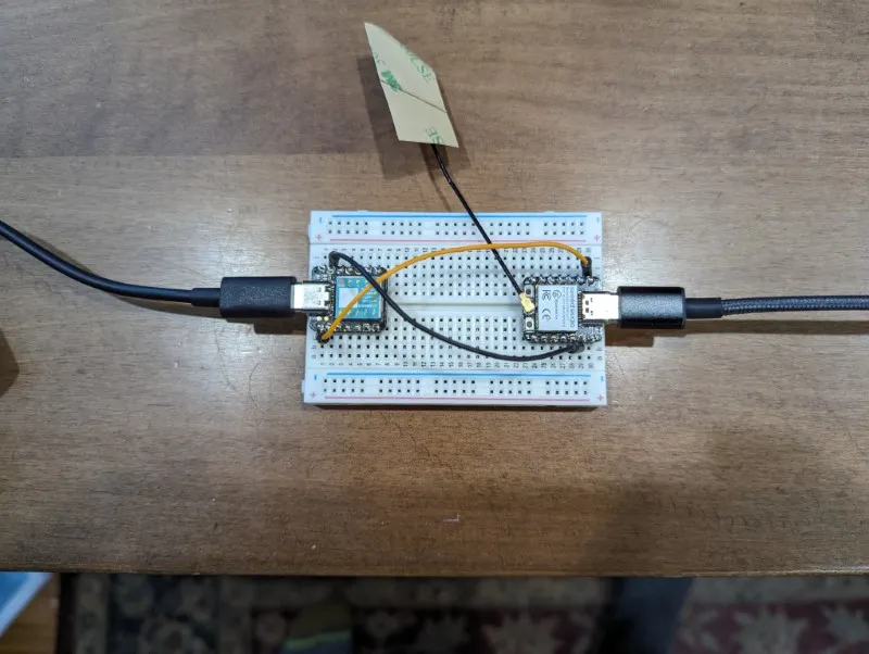
In the image, both devices are Seeed Studio Xiao Arduino-compatible devices and they have very similar pin configurations. I selected these devices because I could easily put two of them on a small breadboard. You can do this with Any Arduino devices, just pay close attention to the pin configurations.
Here I connected the GND pin on both devices using a black wire (black traditionally indicates a ground connection) and I connected the A0/D0 pin on each device to each other.
Note: In the code below I just noticed that I used the A0 pin designator out of habit, but that works fine since the pin is both an analog and digital input/output pin. I could very easily have used D0 to define the pin.
I used the same pin on both devices because I could (and possibly because I have a little OCD), but there's no reason for it other than I wanted to. All that matters is that you select a pin that works as a input and/or output (I/O) and they don't have to be the same pin on each device; use what's available.
With the devices connected, now it's time to write some code.
Sender
For the code sending the signal to another device you must first configure the device for output mode using:
#define PIN A0

pinMode(PIN, OUTPUT);
You only want to do this once, so do it in the Arduino sketch's setup() function.
Next, you must define the code that triggers sending the signal to the other device. I don't have a good scenario to share here, so what I did was put a timer in the loop() function and send the signal for a second (1,000 milliseconds) then wait a second before doing it again. Hopefully the logic in your sketch will be more...sophisticated.
#define DELAY_VAL 1000

void loop() {
  digitalWrite(PIN, HIGH);
  delay(DELAY_VAL);
  digitalWrite(PIN, LOW);
  delay(DELAY_VAL);
}
Here's the complete code for the Sender sketch:
#define PIN A0
// configure the HIGH/LOW delay time (all at once)
#define DELAY_VAL 1000

void setup() {
  Serial.begin(115200);
  delay(1000);
  Serial.println();
  Serial.println("Configuring PIN for OUTPUT");
  pinMode(PIN, OUTPUT);
}

void loop() {
  Serial.println("Setting PIN state to HIGH");
  digitalWrite(PIN, HIGH);
  delay(DELAY_VAL);
  Serial.println("Setting PIN state to LOW");
  digitalWrite(PIN, LOW);
  delay(DELAY_VAL);
}
Load this code on one of the devices then open the Serial Monitor, to watch the text change every second.
Receiver
Setup for the receiver is mostly the same, except that we're configuring the pin for INPUT instead of OUTPUT.
#define PIN A0

pinMode(PIN, INPUT);
In the loop() function, the sketch loops around checking the pin state for the remote Arduino device and writing the state to the Serial Monitor. I added the prevState variable used to help the sketch maintain previous state between reads to use for comparison purposes.
uint8_t prevState = LOW;

void loop() {
  uint8_t state = digitalRead(PIN);
  if (prevState != state) {
    prevState = state;
    Serial.print("PIN status: ");
    if (state == HIGH) {
      Serial.println("HIGH");
    } else {
      Serial.println("LOW");
    }
  }
  delay(25);
}
In this example, the sketch only writes something to the monitor when the remote pin state changes. When it changes, the sketch assigns the current state to the prevState variable so it can compare it again in the next loop with the new state in hand.
Here's the complete code for the Receiver sketch:
#define PIN A0

uint8_t prevState = LOW;

void setup() {
  Serial.begin(115200);
  delay(1000);
  Serial.println();
  Serial.println("Configuring PIN for INPUT");
  pinMode(PIN, INPUT);
}

void loop() {
  uint8_t state = digitalRead(PIN);
  if (prevState != state) {
    prevState = state;
    Serial.print("PIN status: ");
    if (state == HIGH) {
      Serial.println("HIGH");
    } else {
      Serial.println("LOW");
    }
  }
  delay(25);
}
Now, I must mention here that it's not a good idea to tie up the whole processing loop for monitoring pin status. I only wrote it this way for demonstration purposes. Your sketch should leave processing time for other things to happen, moving the pin checking code into a separate function called something like checkRemotePinStatus() and putting other stuff in the loop() function. For more information regarding this approach, take a look at A Better Arduino MicroFogger Controller Redux.
To make it easy to use the same sketch for both the sender and receiver, I created the following code and also published it as a GigHub Gist. Load this code into the Arduino IDE (or your compiler/deployer of choice) and leave #define SENDER as-is for the Sender version, but comment out the line (put two / in front of it // #define SENDER) to compile and deploy the receiver version on a separate device.
/**********************************************************
* Arduino to Arduino Pin Status
* Demonstration sketch
***********************************************************/

// =============================================================
// comment out the following line to build the receiver version
// of this sketch.
// =============================================================
#define SENDER
// =============================================================

#ifdef SENDER

#define PIN A0
// configure the HIGH/LOW delay time (all at once)
#define DELAY_VAL 1000

void setup() {
  Serial.begin(115200);
  delay(1000);
  Serial.println();
  Serial.println("Configuring PIN for OUTPUT");
  pinMode(PIN, OUTPUT);
}

void loop() {
  Serial.println("Setting PIN state to HIGH");
  digitalWrite(PIN, HIGH);
  delay(DELAY_VAL);
  Serial.println("Setting PIN state to LOW");
  digitalWrite(PIN, LOW);
  delay(DELAY_VAL);
}

#else

#define PIN A0

uint8_t prevState = LOW;

void setup() {
  Serial.begin(115200);
  delay(1000);
  Serial.println();
  Serial.println("Configuring PIN for INPUT");
  pinMode(PIN, INPUT);
}

void loop() {
  uint8_t state = digitalRead(PIN);
  if (prevState != state) {
    prevState = state;
    Serial.print("PIN status: ");
    if (state == HIGH) {
      Serial.println("HIGH");
    } else {
      Serial.println("LOW");
    }
  }

  delay(25);
}
#endif
Please let me know if you have any questions.
Next and/or Previous Posts
<< Arduino UDP Broadcast Receiver Eleventy Date-only Filter >>
Header image: Photo by Sahand Babali on Unsplash