 John M. Wargo
Arduino Twinkle Lights

Posted: January 14, 2017 | | Categories: Arduino, Raspberry Pi, Internet of Things (IoT)
Links On This Page
- https://learn.pimoroni.com/tutorial/sandyj/firefly-light
- https://vimeo.com/193441242
- https://vimeo.com/198351699
- https://github.com/johnwargo/Arduino-Twinkle-Lights
- https://adafruit.com/products/2010
- https://adafruit.com/products/2124
- https://adafruit.com/products/1578
- https://adafruit.com/products/259
- https://ikea.com/us/en/catalog/products/10239888
- https://ikea.com/us/en/catalog/products/60277514
- https://adafruit.com/products/896
- https://adafruit.com/products/897
- https://learn.adafruit.com/introducing-pro-trinket/overview
- https://adafruit.com/products/894
- https://adafruit.com/products/895
- https://github.com/johnwargo/Arduino-Twinkle-Lights-Array
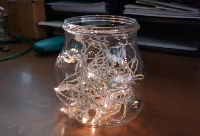
This project is an Arduino variant of the Pimoroni Firefly Light (https://learn.pimoroni.com/tutorial/sandyj/firefly-light) project. Basically you place two strings of battery-powered LEDs into a glass jar and use a microcontroller to fade one strand up while the other strand fades down. The fade up/down process repeats for as long as the microcontroller has power. You could even add 1 or more strands of lights to the project if you want.
Note: removed outdated attachments November 11, 2022
When I discovered the project, I thought it was really cool, but they threw a lot of hardware (a Raspberry Pi, two HATS and a battery) into the solution, so I wanted to see if I could build something with less parts and for less money. This version of project uses an Arduino compatible board (you could use most any Arduino for this project), a battery module and a battery. Here's a video of the white twinkle lights (https://vimeo.com/193441242) in action, and here's a Christmas version (https://vimeo.com/198351699) that uses Red and Green LEDs.
You can find the project's source code at https://github.com/johnwargo/Arduino-Twinkle-Lights. A PDF version of this article is available in the Attachments section (at the very bottom of the article).
Hardware Components
The project (as I've implemented it) uses the following required hardware:
- Adafruit Pro Trinket - 3V 12MHz (https://adafruit.com/products/2010).
- Adafruit Pro Trinket LiIon/LiPoly Backpack Add-On (https://adafruit.com/products/2124).
- Lithium Ion Polymer Battery - 3.7v 500mAh (https://adafruit.com/products/1578).
- Toggle switch; all you need is a SPST switch, but I used a SPDT switch I had lying around.
- A couple inches of 22 or 24 ga stranded wire.
If you chose to use a different microcontroller, you can replace the Adafruit Pro Trinket LiIon/LiPoly Backpack Add-On, which is purpose built for the Adafruit Pro Trinket, with the USB LiIon/LiPoly charger - v1.2 (https://adafruit.com/products/259).
For the white LED version, I used the following hardware:
- Ikea ENSIDIG Glass Jar (https://ikea.com/us/en/catalog/products/10239888).
- 2 Ikea SÄRDAL LED light chain with 12 lights (https://ikea.com/us/en/catalog/products/60277514).
For the Christmas version, I used the following hardware:
- Small Mason jar
- Wire Light LED Strand - 12 Green LEDs + Coin Cell Holder (https://adafruit.com/products/896).
- Wire Light LED Strand - 12 Red LEDs + Coin Cell Holder (https://adafruit.com/products/897).
The LED strand is smaller for the Christmas version, so I used a smaller jar. A benefit of the mason jar is that you can mount the hardware to the underside of the lid, which makes it easier to turn on/off and charge.
Hardware Assembly
Start by assembling the Adafruit Pro Trinket LiIon/LiPoly Backpack Add-On. To enable the use of a SPST switch to power on/off the board, cut the trace connecting the two holes highlighted in the following figure. This disconnects the board's power output, but once you connect a switch between those two holes, you'll be able to control power to the Trinket board.
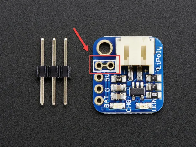
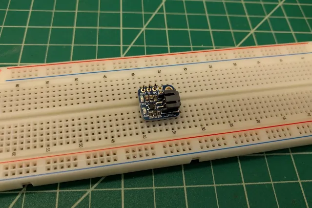
Solder the included headers to the Adafruit Pro Trinket LiIon/LiPoly Backpack Add-On. The header pins connect to the three holes in the lower-left corner of the board as shown in the previous figure. Insert the headers through the board from the bottom (the figure shows the board from a top view) and the black plastic part of the header is flush against the bottom of the board. The easiest way to do this is to insert the header pins in a breadboard, then mount the board on top for soldering as shown in the figure.
Cut two short lengths of wire, then strip the ends and solder an end of each wire to the switch.
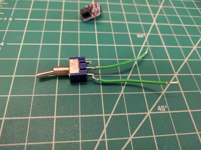
Finally, solder the open wire ends to the switch holes (highlighted in red in Figure 2). Since the hardware will be bumped around in the glass jar, I placed shrink tubing around the solder connections to protect them from being shorted out.
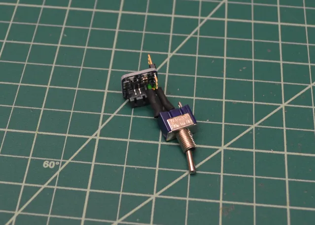
Solder the Adafruit Pro Trinket LiIon/LiPoly Backpack Add-On onto the Arduino Pro Trinket 3V. The board mounts to the Battery, Ground and USB 5V pins shown in the upper-right corner of the board as shown in Figure 6.
To protect the USB connector on the Trinket board, I placed a small piece of electrical tape on top of the board's USB connector. Figure 7 shows the completed board assembly.
Next, you'll need to disassemble the light strand units. Each comes with a battery pack and switch, but since we're driving them from the Trinket, you won't need those parts.
For the Adafruit color LEDs, use a Philips screwdriver to remove the screws from the battery case and open the case. The LED strand connects to the switch and battery contacts as shown in the figure. Make note of which wires are connected to the battery's positive (+) and negative (-) terminals. In my case, the contact in the lower battery slot connects to the battery's positive (+) terminal and the one at the top connects to the negative (-) terminal. I could tell this because the case was embossed with little + and – signs.
When you cut the wires, quickly tie a knot in the negative wire – that way, when you're soldering the wires to the board in the next step, you'll be able to tell which is which. In the strands I had, the positive wire was coated with a white stripe, so it was easy for me to tell the difference between the two wires (without knotting one of them).
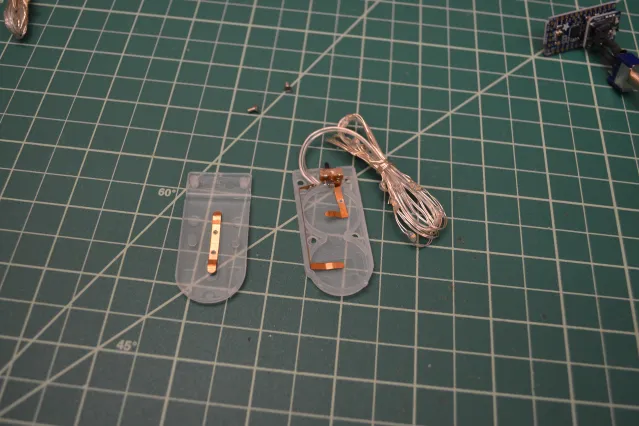
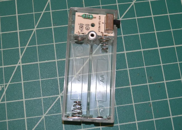
For the SÄRDAL LED light chain units, use a Philips screwdriver to remove the screws from both the top and bottom of the battery case. The LED strand connects to a circuit board inside the battery case, make note of which wires are connected to the battery's positive (+) and negative (-) terminals. As you can see from the following figure, the board is labeled with + and – symbols, so it's easy to tell which wire is which. Tie a simple knot in the negative (-) wire– that way, when you're soldering the wires to the board in the next step, you'll be able to tell which is which.
Optional: To protect the LED circuit, solder a small resistor (in my measurements, the existing white battery pack used a 2.5 Ohm resistor) to each strand's positive (+) wire. I grabbed some 47 Ohm resistors I had lying around to use for this. Be sure to use shrink tubing to cover the open wire and resistor to keep it from shorting out the circuit.
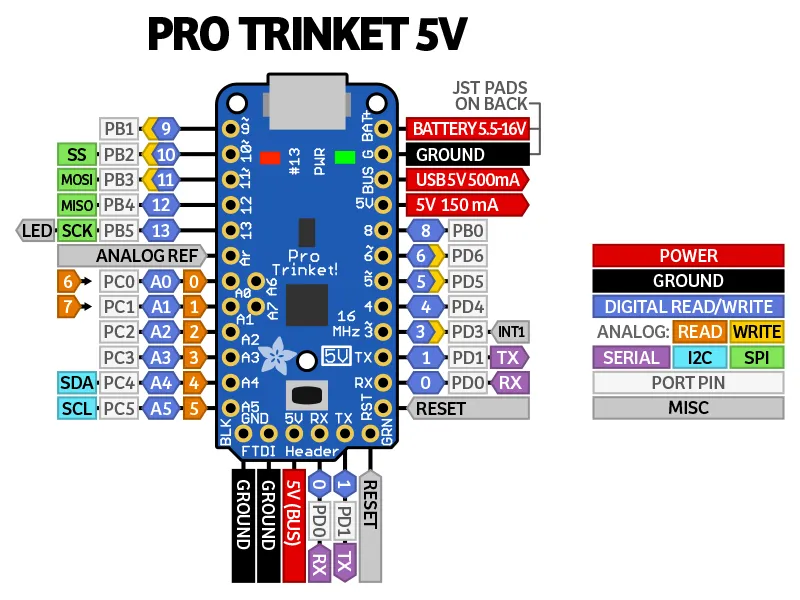
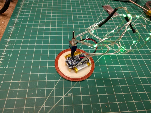
Solder the wires from the LED strands to the appropriate pins on the Arduino Pro Trinket board. For each strand, solder the strand's negative (-) wire to the two GROUND pins in the lower-left corner of Figure 6. Solder each strand's positive (+) wire to pins 9 and 10 in the upper-left corner of the figure. Solder the wires from one strand to pin 9 and the wire from the other strand to pin 10.
NOTE: The picture isn't accurate, when I built this unit, I soldered the wires to the WRONG HOLES. I've since fixed this, and need to take a new photo for here. Sorry.
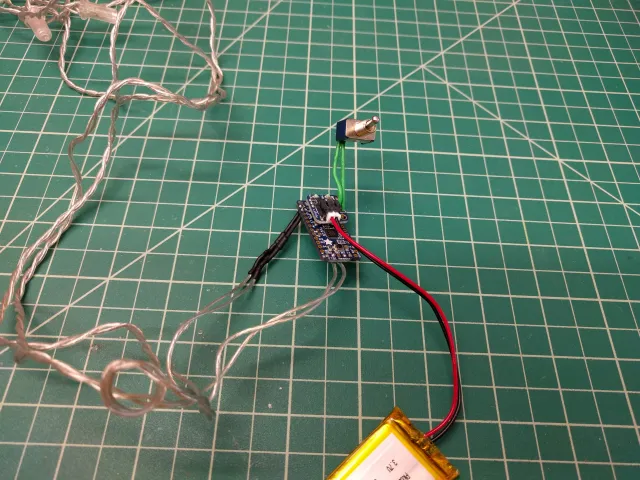
Plug the Lithium Ion Polymer Battery to the Adafruit Pro Trinket LiIon/LiPoly Backpack Add-On.
Connect the Trinket to your PC using a USB cable and download the project's compiled code into the device. The project's code is located in the repository's twinkle_lights.ino file. You can find complete directions on how to setup your development environment and deploy compiled code to the Trinket in the Trinket tutorial (https://learn.adafruit.com/introducing-pro-trinket/overview).
Stuff the whole contraption into the jar, turn it on, and close the lid. You're done!
Mounting
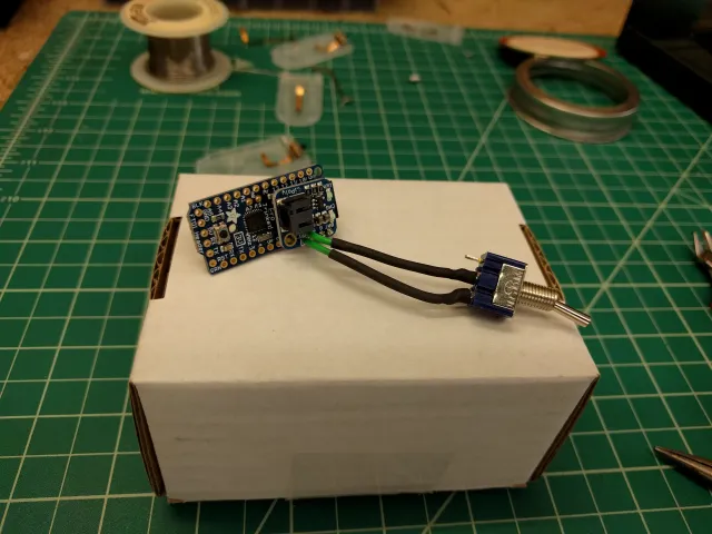
For the white lights, the strand is so long and the lights so large, that stuffing the whole contraption in a jar works quite well. The hardware just sits at the bottom of the jar and is hardly noticed, especially in darker rooms. To charge the battery, or flip the switch, you'd have to pull the whole assembly out of the jar and put it back when you're done.
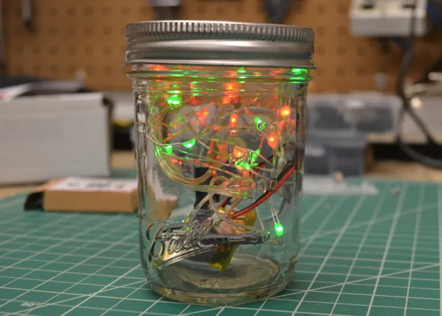
In Figure 11, the lights are rather small and the strand short, so the hardware stands out more prominently. The mason jar implementation provides an interesting option for mounting the hardware. I drilled some holes in the lid, and using two standoffs and screws, mounted the hardware to the underside of the lid. I then used two-sided tape to adhere the battery to the lid, underneath the microcontroller (see Figure 12). With this approach, you simply remove the top to charge the battery or flip the switch, reducing stress on the assembly.
The Project's Code
The project's code is pretty simple. At the beginning, you'll find code that initializes the variables used by the application:
//Analog output pin assignmentsIf you connect the LED strand's positive wires to different Trinket Analog output pins, you'll need to change the values assigned to pin0 and pin1.
Right now, the application powers the LED strands from 0 to 255 as the strand brightens, and from 255 to 0 as the strand darkens. As each voltage value is assigned to the output pin, the application delays for delayVal milliseconds. So, to make the strands fade more quickly, reduce the number assigned to this variable. To make the strands fade more slowly, increase the value assigned to this variable.
The setup method initializes the variables the application uses to track which strand (by its output pin number) is brightening and which is darkening. Since we're just starting, and both strands are dark, the code starts by fading pin1up to maximum output voltage. Once it's done, everything is initialized and its time to start flipping both strands.
void setup() {
  //Initialize the up and down pin designators
  upPin = pin1;
  downPin = pin0;

  //The setup function initializes the application
  //In this case, we'll just start by winding strand 1 up to
  //full illumination
  for (int i = 0; i <= maxAnalog; i++) {
    //Write the voltage value
    analogWrite(upPin, i);
    //Pause for a little while
    delay(delayVal);
  }
  //Wait a second before continuing
  delay(1000);
}
The loop method flips the up and down pin variables (upPin and downPin), then fades the strand connected to upPinup to maximum voltage while simultaneously fading the strand connected to downPin down to 0. When it's all done, it waits for a second (1000 milliseconds) before repeating the process again.
void loop() {
//Variable to keep track of one of the pin assignments
//as we swap them
int tmp;
//Hold on to the current upPin value
tmp = upPin;
//set upPin to the downPin value
upPin = downPin;
//Then set downPin to what used to be in upPin
downPin = tmp;
//Look through the voltage output values (from 0 to 255)
//increment by 1
for (int i = 0; i <= maxAnalog; i++) {
   //Drive the upPin up to maxAnalog
   analogWrite(upPin, i);
   //While simultaneously driving downPin down to 0
   analogWrite(downPin, maxAnalog - i);
   //Pause for a little while
   delay(delayVal);\>
}
//Wait a second before continuing
delay(1000);
}
Variations
Make a version of this for different holidays. For example, Adafruit sells white and blue LED strands, so you can easily make a US 4th of July edition of the twinkle lights using the following parts:
- Wire Light LED Strand - 12 Red LEDs + Coin Cell Holder (https://adafruit.com/products/897).
- Wire Light LED Strand - 12 Cool White LEDs + Coin Cell Holder (https://adafruit.com/products/894).
- Wire Light LED Strand - 12 Blue LEDs + Coin Cell Holder (https://adafruit.com/products/895).
The code must be adjusted to sequentially fade the light strands – first red, then white, and finally blue, before repeating the series. My code for this implementation can be found at https://github.com/johnwargo/Arduino-Twinkle-Lights-Array.
Next and/or Previous Posts
<< Epic UX Failure at Bandsintown Amazon Cancel and Reorder >>
Header image: Photo by Sahand Babali on Unsplash