 John M. Wargo
Using the Seeed Studio Raspberry Pi Relay Board

Posted: February 15, 2017 | | Categories: Raspberry Pi, Internet of Things (IoT)
Links On This Page
I had an idea for a project, a Raspberry Pi-based power controller for my media center. I searched around for relay boards, and discovered the Seeed Studio Raspberry Pi Relay Board v1.0 https://seeedstudio.com/Raspberry-Pi-Relay-Board-v1.0-p-2409.html, so I thought I'd give it a try.
Note: At the time, this was the only directly-mountable relay board I could find for the Raspberry Pi. Since then, I found another one in the ModMyPi PiOT Relay Board (https://modmypi.com/raspberry-pi/breakout-boards/modmypi/modmypi-piot-relay-board). I'll play with that one soon and publish my findings here; stay tuned.
When I finally got around to playing with the hardware, I used (or should I say tried to use) Seeed Studio's Wiki Page for the board (https://wiki.seeed.cc/Raspberry_Pi_Relay_Board_v1.0/) to guide my efforts. Unfortunately, I quickly learned that the article was incomplete and didn't have everything I needed to work with the board. I mounted the board on my Raspberry Pi, powered it up, ran their sample test application, and got nowhere. It simply didn't work.
I sent Seeed Studios an email asking for help and posted a couple of questions on their community forums, but had to wait more than a month to get a response. When I finally did hear back, it was to let me know that they were on vacation and it would be an even longer wait for help. Sigh. Finally, they contacted me and offered to help.
After another week of sending them screen shots, I finally got useful information and was able to get the board operational. The purpose of this article (and associated Github repository at https://github.com/johnwargo/Seed-Studio-Relay-Board) is to show you how to use the board so you'll avoid the issues I had.
Update: After publishing this article, I shared this information with the folks at Seeed Studio. They then updated their Wiki article with information directly copied from this article and the associated GitHub repository readme file. So, you'll finally find good, useful information on their product Wiki page - because I wrote it.
In the Github repository, I shared the code Seeed provides to test the board (so that you can grab it using git rather than copying and pasting it from a Wiki page) plus a Python module (and associated test application) you can leverage to use the relay board in your own Raspberry Pi projects. I also created a complete Raspberry Pi relay controller application (using Python and Flask); I'll publish information about that soon.
The steps for installing the board and verifying that it works includes the following steps:
- Mount the Relay board on the Raspberry Pi
- Enable the Raspbian I2C software interface
- Validate that the Raspberry Pi recognizes the board
- Run some Python code to exercise the board
In the rest of this article, I'll show you how to do all of those things.
Mounting the Relay Board
Mounting the board is easy, it comes with the appropriate female headers you need to mount it on any Raspberry Pi board with male headers. Note: You'll have to add male headers to the Raspberry Pi Zero to use the board.
Seeed Studio recommends putting some electrical tape on top of the Raspberry Pi Ethernet port before mounting the board. If you mount the board without using standoffs (as I've done in the example figure below), there's a chance the board will make contact with the Ethernet port housing and cause a problem.
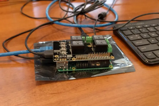
For a production project, I'd definitely recommend using standoffs to hold the two boards in place.
The relay board is configured for an older Raspberry Pi with a 26 pin header, so when you connected it to a Raspberry Pi with 40 pin headers, you'll need to shift it all the way to the side like I've shown in the figure. If you don't align the pins correctly, you'll have problems later as it simply won't work.
Enabling I2C
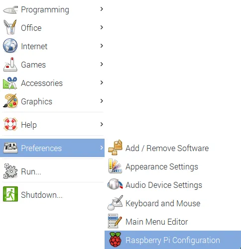
The relay board communicates with the Raspberry Pi through an I2C interface (https://en.wikipedia.org/wiki/I%C2%B2C). This interface is disabled by default in the Pi's Raspbian OS, so you'll have to turn it on before you can use the board. Power up the Pi and let it boot to the graphical interface. When it's up and running, open the Pi menu, select Preferences, then Raspberry Pi Configuration as shown in the following figure:
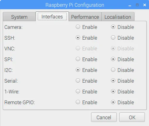
In the window that opens, select the Interfaces tab as shown in the following figure. Enable the option next to I2C as shown in the figure and click the OK button to continue. When you reboot the PC, the Pi should see the relay board. In the next section, we'll verify that the Pi sees the relay board.
Validating the Raspberry Pi Sees the Relay Board
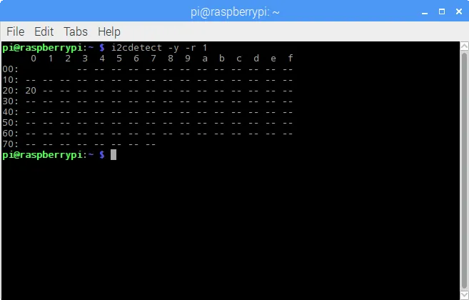
With the I2C interface enabled, it's time to make sure the Raspberry Pi sees the relay board. Open a terminal window on the Pi and execute the following command:
i2cdetect -y -r 1The application will display a dump of the recognized I2C devices as shown in the following figure. In this example, there's only one I2C board on the system, the relay board configured at an address of 20. You'll see how this value is important later in this article.
You're supposed to be able to use switches on the relay board to set the I2C address, but the Seeed Studio Wiki page contains no information on how that is accomplished. There are 4 DIP switches on the board, but your guess is as good as mine as to what they do. So, let's see what happens when you change them.
There are four switches, three labeled A0 through A2, and one labeled NC. I'm going to assume the NC means No Connection and leave that out of my analysis. Each switch has a high and a low setting, so the following table will lay out how to use them to set an I2C address for the board:
Table 1: Relay Board Switch Settings
| A0 | A1 | A2 | Address |
|---|---|---|---|
| High | High | High | 20 |
| Low | High | High | 21 |
| High | Low | High | 22 |
| High | High | Low | 24 |
| High | Low | Low | 26 |
| Low | Low | Low | 27 |
Running the Seeed Studio Test Application
The Seeed Studio Wiki includes the source code for a sample application you can run to test your application. The source code is listed on the Wiki, but when you copy it and paste it into your Python development environment, it won't run correctly. Python uses indentation to indicate blocks of code, and when you copy the code from the Wiki, it's not formatted properly for use. To make it easier for you, I formatted the code and included it in the Github repository listed earlier. Grab the code from there and you'll be able to easily complete the following step.
To run the test application, open a terminal window, navigate to where you've extracted the sample application and run the application using the following command:
python ./seeed_relay_test.py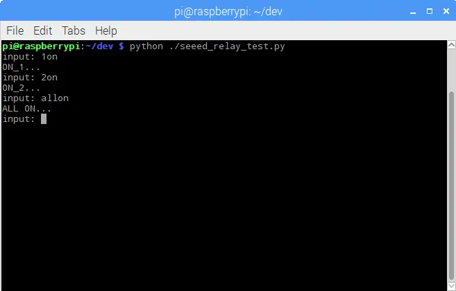
When prompted for input, you'll type commands to turn the relays on and off:
- Typing
1on,2on,3on, or4onand pressing enter will cause the specified relay to turn on. - Typing
1off,2off,3off, or4offand pressing enter will cause the specified relay to turn off - Typing
allonoralloffwill turn all relays on or off.
Using The Python Module
To use the module in your own Python applications, copy the module (relay_lib_seeed.py) into your project folder, then import the module in your Python application by adding the following line to the beginning of your application:
from relay_lib_seeed import *This exposes a series of functions to your application:
relay_on(int_value)Turns a single relay on. Pass an integer value between 1 and 4 (inclusive) to the function to specify the relay you wish to turn on. For example: relay_on(1)will turn the first relay (which is actually relay 0 internally) on.
relay_off(int_value)Turns a single relay on. Pass an integer value between 1 and 4 (inclusive) to the function to specify the relay you wish to turn on. For example: relay_on(4) will turn the first relay (which is actually relay 3 internally) off.
relay_all_on()Turns all of the relays on simultaneously.
relay_all_off()Turns all of the relays off simultaneously.
The module exposes a configuration value you will want to keep in mind as you work with the board:
# 7 bit address (will be left shifted to add the read write bit)DEVICE_ADDRESS = 0x20Remember that value? 20? The board defaults to this address. If you change the switches on the board, you will need to update this variable accordingly.
To see the module in action, open a terminal window on the Raspberry Pi, navigate to the folder where you extracted this repository's files, and execute the following command:
python ./relay_lib_seeed_test.pyThe application will:
- Turn all of the relays on for a second
- Turn all of the relays off
- Cycle through each of the relays (1 through 4) turning each on for a second
The module will write indicators to the console as it performs each step as shown in the following figure:
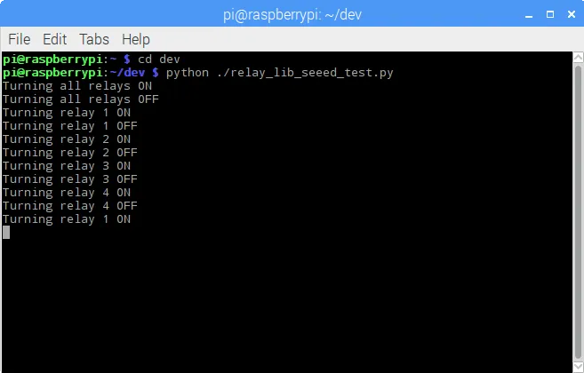
LEDs on the relay board (one for each relay) will illuminate when the relays come one. On my board, they weren't in sequence, so don't expect them to light in order.
The code that does all this looks like the following:
# turn all of the relays on
relay_all_on()
# wait a second
time.sleep(1)
# turn all of the relays off
relay_all_off()
# wait a second
time.sleep(1)
# now cycle each relay every second in an infinite loop
while True:
    for i in range(1, 5):
        relay_on(i)
        time.sleep(1)
        relay_off(i)
That's it, that's all there is to it. Enjoy.
Next and/or Previous Posts
<< Raspberry Pi Relay Controller A Site In Transition >>
Header image: Photo by Harrison Broadbent on Unsplash