 John M. Wargo
IoT Component Manufacturers Ignoring Mounting Needs

Posted: October 8, 2023 | | Categories: Internet of Things (IoT)
I'm working on a Halloween project that requires some external hardware components mounted on different things. In this case, it's my Sleeping Dragon in a Mailbox project and I'm trying to figure out how to mount my project's LEDs and mm Wave RADAR devices. Let me explain...
For the dragon's eyes (inside the mailbox) I selected the NeoPixel Ring - 12 x 5050 RGB LED with Integrated Drivers. The NeoPixel ring is awesome, but it has some flaws. Take a look at the image below.
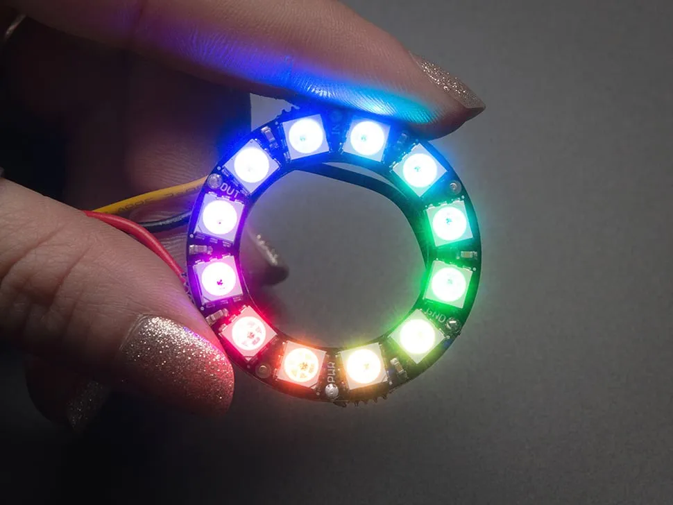
From a mounting perspective it looks like the person who designed it didn't take into account how the ring would actually be used in a project outside of perhaps sewing it into a piece of clothing.
The ring has three required connections, four if you want to connect the ring to other NeoPixel devices. Unfortunately, the solder points for the 4 possible connections are distributed around the ring. This means from a wiring perspective that you must split your wires and spread them around the ring. That works, but it's clunky - depending on the project, you could have these single wires spreading across the project.
If you think about how someone like me would use this device in a project, what I want is all of the connections grouped together one one side of the ring. If daisy changing multiple rings together, I'd want the three input connections on one side, and three output connections on the other side, just like they did for the Breadboard-friendly RGB Smart NeoPixel. That just makes more sense.
With this approach, the wiring is clean, and you can use bundle of wires and keep them together instead of spidering the wires across the back of the ring.
Now, when it comes to mounting the ring in a project, the designers didn't address that as well. If you're sewing the ring into a project, then you can loop thread across the ring and tie it in that way. But when you're mounting the ring in a project, say for example as Dragon Eyes in a Mailbox, there's no mechanism built into the ring to allow it.
I used NeoPixel rings in other projects and resorted to using Hot Glue to glue the ring to an enclosure. That works, but it's not sturdy or reliable. The glue could break off at any time leaving my project in shambles.
What Adafruit should have done here was leave an extra border on the inside and/or outside of the ring with mounting holes (and publish the sizes of the holes so customers can easily find the right screw or bolt to use for mounting) to use for, you know, mounting. That should be a requirement for any product - mounting holes. Make them little nubs (with bolt hole) that can be broken off if not needed.
Even if you don't want to support mounting holes, at least provide that border so users can cut a groove in a piece of wood or plastic and slide the ring in place.
A while back, I published an article here about the DFRobot mmWave RADAR device. It's a great device and easy to use (as I described in the article) but now I'm trying to mount it in my project and it looks like my only option is to use Hot Glue again.
Here's a picture of the board:

Unlike the NeoPixel Ring, it does have mounting holes, but the mounting holes are:
- Too small, I can't seem to find screws to use here, unless I go down to less than 2mm.
- Right next to the solder points for the wiring harness.
Putting the mounting holes on either side of the soldered connections only proves that the designer of this board wasn't paying attention to how this board would be used in projects.
If I use the bolt holes to mount the board to my project, I lose the ability to solder wires to the board. That makes absolutely no sense.
DFRobot should absolutely put the mounting holes somewhere else on the board and definitely used 4 holes instead of two as Seeed Studio did with their 24GHz mmWave Sensor - Human Static Presence Module Lite. When you look at the Seeed Studio board, you'll notice that they put mounting holes in the four corners of the board (excellent) plus put wire connections in the middle of the back of the board away from the bolt holes.
Now, the Seeed Studio board has some issues as well, the wire connections aren't solder points, but at least they gave me a way to mount the board.
For either board, another mounting option is to put a little border on the board - don't got for the smallest possible size, add a little room which allows users to slide the board into a groove to hold it in place when bolt holes aren't an option.
What I'm asking for here is Product Designers to actually think about application as well as functionality when designing these boards. Deliver a full and complete product which includes:
- Attention to what the device should do (functionality)
- Attention to how the device will mount in a project (application)
- Complete product specifications such as the dimension of the bolt holes (which neither DFRobot or Seeed Studios publish)
- Complete and well documented SDK
Time to go heat up the glue gun to mount the mmWave sensor and LED ring to my project.
Next and/or Previous Posts
<< All Things Open 2023 Session Materials American Airlines Poor Unsupported Browser Implementation >>
Header image: Photo by Robin Glauser on Unsplash.