 John M. Wargo
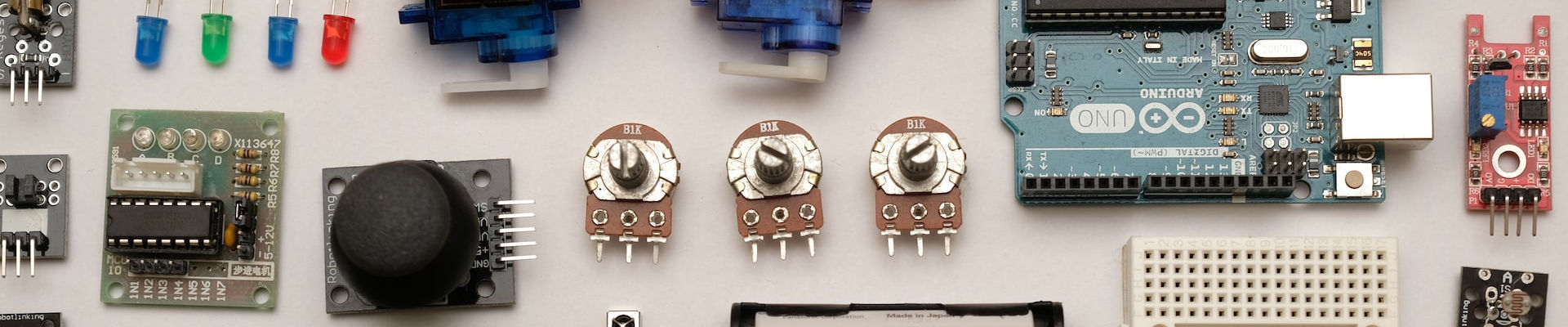
Building a Better Light Timer

Posted: March 24, 2018 | | Categories: Internet of Things (IoT), Arduino
Links On This Page
- https://makezine.com/2018/03/19/control-electronic-relays
- https://adafruit.com/product/3010
- https://adafruit.com/product/2922
- https://adafruit.com/product/2886
- https://adafruit.com/product/2830
- https://adafruit.com/product/268
- https://amazon.com/gp/product/B00OJZPMD2
- https://adafruit.com/product/1995
- https://amazon.com/gp/product/B00HKIQG3U
- https://github.com/johnwargo/arduino-rtc-relay-static
- https://git-scm.com
- https://learn.adafruit.com/adafruit-feather-m0-adalogger/setup
Make Magazine recently published an article of mine entitled Relays 4 Ways (they called it4 Ways to Control Electronic Relays, but I like my title better), you can find the article here: https://makezine.com/2018/03/19/control-electronic-relays This article was intended to accompany the Relays 4 Ways article as an example of a complete project using one of the components described in the article. For whatever reason, the folks at Make didn't want this one, so I get to publish it here. Enjoy!
Introduction
If you're a homeowner like me, you probably setup one or more light timers in your house whenever you leave for vacation. These devices are great, they turn any connected device (usually a light fixture) on and off on an adjustable schedule. Many devices let you set two on/off time pairs (one in the morning and another at night for example) while more sophisticated (read expensive) devices let you set as many as you want.
The problem with these timers is that you must manually set the on/off times, plus you must ensure the device clock is set to the proper time every time you plug them in. If you're out of town and the power goes off for any reason, when the power comes back on, the time will be off, and suddenly this inexpensive home security device turns your lights on and off at unexpected times instead of when you want it to, almost broadcasting to potential burglars that you're not home.
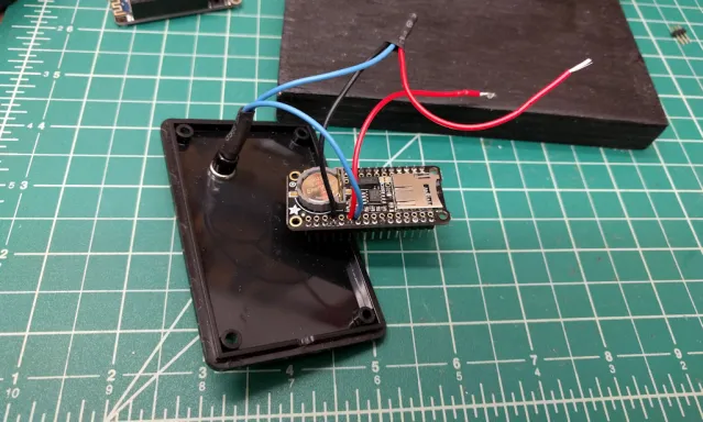
To help get around these limitations, its time for a better light timer. With this project, you'll build a microcontroller-driven light timer that sets its own internal clock automatically via the Internet and turns the light on and off on an exact schedule. The project uses a Wi-Fi enabled Arduino device, and uses the device's Wi-Fi connection to query an Internet time server for the current time. I used a real-time clock (RTC) module to store the time between sessions just in case the device can't connect to the Internet to determine the current time on startup. Figure 1 shows the completed project.
What's missing from the photo is power for the microcontroller; for this project I used a simple smartphone charger. To run this project, you'll need two available power outlets, one for the light fixture, and the other to power the light timer.
Within the project's code, you'll define an array of on/off times that controls when the lights go on and off. I also added a push button to the project so you can turn the lights on/off manually as needed.
Note: Switching AC Power (110V in the US or 220V elsewhere) is dangerous; if you don't do it right, you can harm yourself or even start a fire. To eliminate most of the risk in working with high voltages, this project uses a power pigtail to manage the power control aspect of the project. You'll learn more about this component later.
Components
For this project, I used the following components:
- Adafruit Feather M0 WiFi - ATSAMD21 + ATWINC1500 (https://adafruit.com/product/3010).
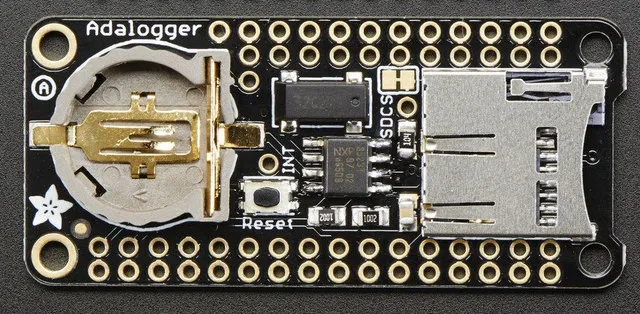
- Adalogger FeatherWing - RTC + SD Add-on (https://adafruit.com/product/2922).
- Feather Header Kit - 12-pin and 16-pin Female Header Set (https://adafruit.com/product/2886).
- Feather Stacking Headers - 12-pin and 16-pin female headers (https://adafruit.com/product/2830).
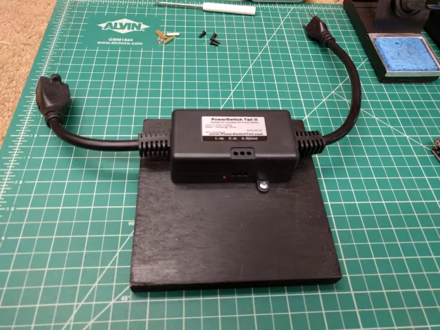
- Powerswitch Tail II (https://adafruit.com/product/268).
- SPST momentary push button (https://amazon.com/gp/product/B00OJZPMD2).
- 5V 2.4A Switching Power Supply with 20AWG Micro USB Cable (https://adafruit.com/product/1995).
- Project enclosure – For my project, I used the Hammond 1591M, a 3.3” X 2.2” X 0.8” enclosure (https://amazon.com/gp/product/B00HKIQG3U).
- An approximately 6 x 6 X ¾ piece of plywood, painted black (or your color of choice).
- 4 #8 x ¾ wood screws (or equivalent).
- A few lengths of 20 or 22 gauge wire: black, red and some other color of your choice (I used blue).
About the Powerswitch Tail
The Powerswitch Tail (PT) is basically a box containing a relay with its switched connection wired across one of the conductors in an AC power plug. When you apply a specific voltage (normally between 3V and 5V) to the input connections on the PT (shown with two red wires connected to it in the figure) the relay triggers and AC current passes through the power cord. The PT is normally wired for normally open (NO) operation, but you can usually reconfigure the PT for NC operation as well.
Note: Refer to my article Relays 4 Ways for more information about relays.
For this project, I used an Arduino-compatible microcontroller to apply that voltage (under program control, of course) to the PT input triggering the relay inside. When the microcontroller sends a voltage to the PT, its relay closes and AC power flows through, powering whatever is connected to it. When the microcontroller removes the voltage, the relay opens and power stops flowing through the PT.
Note: For this project, must provide two power sources, one to power the microcontroller (a smartphone charger providing 5V DC) and another to power the electrical device connected to the PT (110V or 220V AC depending on where you live).
Assembling the Hardware
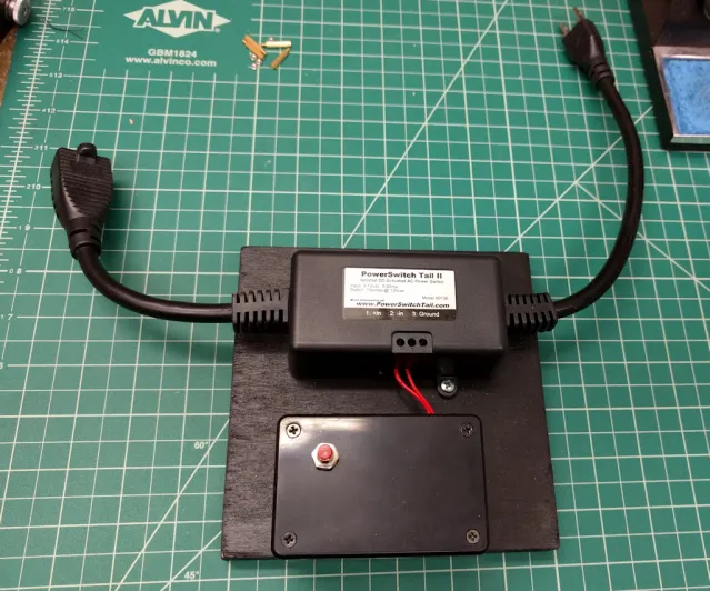
The Feather MO Wi-Fi and FeatherWing boards are sold as stand-alone boards; even though they're designed to stack on top of each other, there's no hardware included to connect them together. That's why I added the female and stacking headers to the project. You'll use the stacking headers with the FeatherWing board and the female headers with the Feather board as shown in Figure 2.
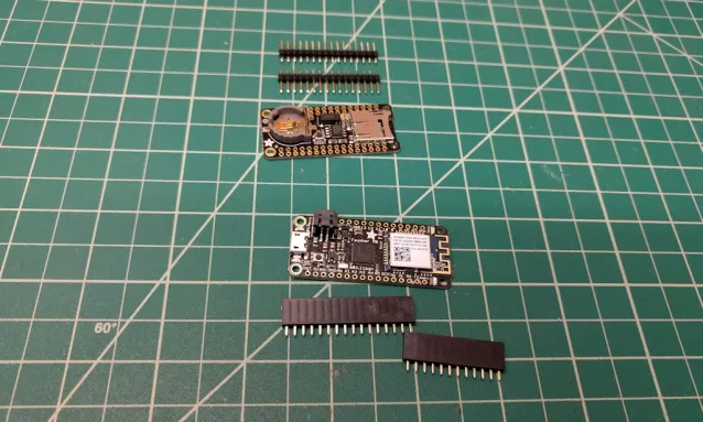
Mount the female headers on the top of the Feather; you'll want the header sockets facing up so that you can mount the FeatherWing board on top of the Feather later. You can see what this looks like in Figure 3. The Feather boards don't use the same number of header pins on each side of the board, so pay attention to which headers you put on each side. Flip the board over and solder the header pins, making sure that the headers are flush against the surface of the board.
Next, insert the shorter posts from the stacking headers through the outside holes in the bottom of the FeatherWing board. If you look closely at the board (Figure 4), you'll notice that the board has two sets of pin holes. The outside holes are for mounting the headers, the inside holes are for external connections to those pins; you'll see how this works later. For now, make sure you place the headers in the correct set of holes; you won't be able to connect the FeatherWing to the Feather board later if you make a mistake here.
With the headers in place, solder the pins in place on the top of the board. With this work done, you should be able to mount the FeatherWing board on top of the Feather Mo board as shown in Figure 3. Don't do this yet, I'm just letting you know that you could do it if you wanted to. OK, if you're impatient like me, or you just want to check your work, go ahead and connect the boards – just be careful separating them so you don't bend the header pins.
Mount the Powerswitch Tail on the board, positioning the device close to one side of the board. You'll need to leave room for the enclosure, so position both on the board as you sort out the position for the PT. Make sure that the connections (the three holes shown face of the device) on the PT are facing the open/empty portion of the board as shown in Figure 5. Drill pilot holes in the board where you want to mount the device, then use two screws to secure it to the board in the selected position.
Note: You're going to mount the project's enclosure on a board next to the PT, so do some planning now for where you want to make holes in the enclosure for the wires that pass through. You're going to run the power cable through the enclosure to power the Feather and FeatherWing boards and you'll also have two wires between the enclosure and the PT. For my version of this project, I ran the power cable through the right side of the enclosure (not shown in Figure 1) so both the light fixture power and enclosure power come in from the right side of the assembly.
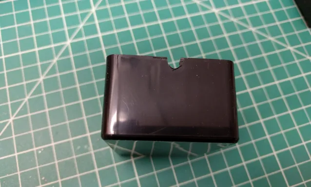
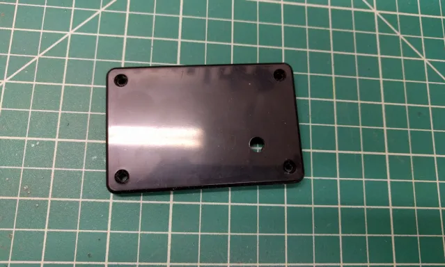
Using a drill or drill press, drill a hole in one end of the enclosure bottom for the power cord. The hole should be big enough for the power cable to fit in loosely. I always find that its easiest to drill this hole with the enclosure cover on, that way the plastic doesn't bend as you put pressure on it with the drill. Cut through the hole to the top of the enclosure to make the opening U-shaped as shown in Figure 6. Make sure that the hole is low enough that the USB power cable can fit through the hole with the lid on.
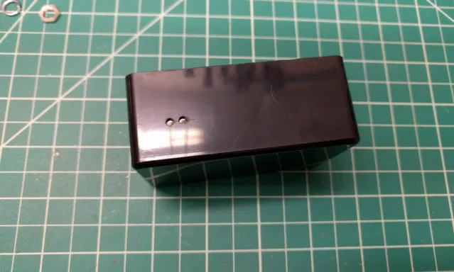
Drill a hole in the side of the enclosure for the wires that will connect from the microcontroller to the PT as shown in Figure 7. I drilled two holes so I could run one wire through each, but you could easily use only one hole – just make sure its big enough for two wires.
Remove the nut and washer from the push button and select a drill bit that is only slightly larger than the opening in the washer. Using that drill bit, drill a hole in the enclosure lid for the push button. You'll want to drill the hole with the lid attached to the enclosure (to keep the lid from flexing as you drill). Make sure you're not drilling the hole too close to the edge as that will overlap the side of the enclosure. Position the button hole out of the way (lower-left or lower-right corner of the lid) as shown in Figure 8.
Solder two 3” wires to the push button connectors as shown in Figure 9. To keep any of the project component from shorting the button, I used shrink tubing to cover the soldered connections as shown in the figure.
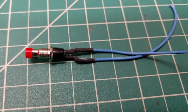
Mount the push button in the enclosure lid, making sure the button is on top of the lid. Use the washer and nut to secure the button in place.
Cut three wires about 4 inches long: one black and two red. Solder one of the push button wires to the black wire and one of the red wires. At this point, you'll have three wires soldered together as shown in the top of Figure 10. Use electrical tape or shrink tubing to cover the soldered connection.
OK, before we go any further, lets talk about the connections we'll make to the Feather board. Remember, we soldered female headers to the Feather, so there's no open connections for us to use on that board. However, on the FeatherWing, there's an extra set of connections I said we could use for external connections. Those connections connect to the corresponding connectors on the FeatherWing that are connected to the same pins on the Feather. Basically, those extra connectors are a pass-through to the corresponding pins on the Feather board.
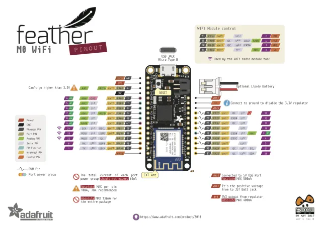
For this project, we need one input and one output: the input comes from the push button, and the output is the voltage connection to the PT. In a few minutes, we're going to connect the output to the Feather's A1 connection, and the push button to the Feather's A2 connection. Take a moment and study Figure 11, it shows the Feather board pinouts. On the left side of the board you'll see the three connections we're going to use for this project: Ground (labeled GND in the figure), A1, and A2.
Note: Use Figure 10 as a visual reference for the next three steps.
Solder the open end of the black wire to the GND pin on the FeatherWing board. If you look at Figure 4, the connection you want is the 4th in from the left on the lower half of the board.
Solder one end of the extra red wire to pin A1. On Figure 4, this is the 6th connector from the left on the lower half of the board.
Solder the free wire from the push button to pin A2. On Figure 4, this is the 7th connector from the left on the lower half of the board.
When you're done, you should have two red wires not connected to anything, and everything else connected to the FeatherWing. These two red wires are what connects the Feather board to the PT.
Mount the FeatherWing on the Feather. To do this, just align the pins on the FeatherWing with the header sockets on the Feather and push them together gently.
Select a drill bit that matches the thread width of the wood screws. Drill two holes in the bottom of the enclosure. Drill slightly smaller pilot holes in the board, then use the two remaining wood screws to secure the enclosure to the board.
Push the two red wires through the hole (or holes) in the side of the enclosure facing the PT. Connect the wires to the appropriate connectors on the PT. You'll have to look at the instructions for your PT to determine which ones to use.
At this point, everything is wired and connected, its time to download and install the code.
The project's code can be found at https://github.com/johnwargo/arduino-rtc-relay-static To get the code, you can download a zip file containing everything and extract it in a folder on your system.
If you have Git installed (macOS comes with it installed by default, on Windows you'll have to install it yourself from https://git-scm.com), you can download it by opening a terminal window, navigating to a folder where you want to extract the project's code, and executing the following command:
git clone https://github.com/johnwargo/arduino-rtc-relay-staticFollow the instructions to setup the Arduino IDE found in the Feather tutorial at https://learn.adafruit.com/adafruit-feather-m0-adalogger/setup
Before you can use the project's code, you must first configure it. The application needs to know the settings for your Wi-Fi network so it can connect to the internet and get the current time. The application also needs to know when to turn your lights on and off. Lets start with the Wi-Fi configuration first.
The project's Wi-Fi configuration settings are stored in a file called wi-fi-config.h. When you open the file in the IDE, you should see the following:
// Populate the defines below with the settings for your Wi-Fi network
// Network SSID (name)
#define wifi_ssid ""
// SSID password (use for WPA, or use as key for WEP)
#define wifi_pass ""
Populate the wifi_ssid and wifi_pass values with the appropriate values for your network. The wifi_ssid refers to the network name for your Wi-Fi network. This is the value you'll see when you open your smartphone's Wi-Fi settings and your network appears in the list of available networks. The wifi_pass value refers to the password you need to connect to the Wi-Fi network specified in wifi_ssid.
So, if your local Wi-Fi network is called MyNetwork and the password for MyNetwork is “some ridiculous password” then your wi-fi-config.h file should look like this:
// Populate the defines below with the settings for your Wi-Fi network
// Network SSID (name)
#define wifi_ssid "MyNetwork"
// SSID password (use for WPA, or use as key for WEP)
#define wifi_pass "some ridiculous password"
Save your changes to the file before continuing.
Next, open the project's rtc-relay-static.ino file. Near the top of the file, you should see a constant definition for your local time zone:
//Set the time zone using the time zones listed in constants.h.
//You'll have to manually switch the device from standard time to daylight
//time during the summer if you live in an area that observes daylight time.
const int timeZone = EST;
Right now, the application is configured for Eastern time zone (that's where I live). If you live in a different time zone, change this value to one of the available options in the constants.h file. I didn't list all the time zone options in this file, so if your time zone isn't listed, you're going to have to add it to the file before making the change to the timeZone value in the rtc-relay-static.ino file.
Finally, the app knows when to turn the lights on and off based on settings defined in the slots array shown below:
//Populate the following variable with the number of rows in the slots array
//I'm doing this way because Arduino doesn't have an easy way to determine
//the size of an array at runtime, especially multidimensional arrays.
#define NUMSLOTS 2

//Use the Slots array to define when the relay(s) go on and off
//Slots array values: {onTime, offTime };
// Examples:
// Turn the relay on at 6:00 AM, turn it off 8:00 AM
// { 600, 800 },
// Turn the relay on at 5:00 PM turn it off at 11:00 PM.
// {1700, 2300}
// Turn the relay on at 5:30 AM, turn the relay off at 7:00 AM.
// {530, 700}
int slots[NUMSLOTS][2] = {
 { 600, 800 },
 {2000, 2300}
 //BE SURE TO UPDATE THE NUMSLOTS CONSTANT IF YOU ADD/REMOVE
 //ROWS FROM THIS ARRAY
};
Currently, the application is configured to turn the lights on at 6 AM and turn them off at 8 AM. Later in the day, it will turn the lights on again at 8 PM and off at 11 PM. Do you see that in the code? Hint: time values are stored in 24 hour format.
Right now, the slots array is a two-dimensional array with two rows and two values for each row. Each row consists of an on time and an off time. You can have as many on/off times (rows) defined as you want. The C language on the Arduino platform doesn't support dynamically sized arrays, so when you add or remove a row to this array, you must also change the value in NUMSLOTS to correspond to the number of rows in the array.
Make whatever changes you want to the on/off times, then save your changes to the file. Use the Arduino IDE to load the application to the Feather board, connect the power supply to the Feather board, secure the top on the enclosure, and you're ready to go.
To test the assembly:
- Plug the Powerswitch Tail into a wall outlet.
- Plug a light fixture or other electric appliance to the other end of the Powerwsitch Tail.
- Plug the project's power supply into another outlet.
- Give the hardware some time to initialize and connect to the network.
- Push the push button for about a half-second or more to toggle the Powerswitch Tail relay manually.
That's it, you're done! The project code is the most sophisticated Arduino code I've written. Spend some time reading through the code to see how it verifies its configuration and that it has the correct time and knows how to connect to the Internet to update it.
Next and/or Previous Posts
<< Pug and JavaScript Functions Advancing Technology in Wilmington Meetup >>
Header image: Photo by Robin Glauser on Unsplash.